
The highest temperature rating isn’t the whole story: the thermal barrier performance of a bi-metal heatbreak also depends on how its materials manage heat, limit heat creep and let filament move smoothly. Titanium-alloy designs are listed to 300°C, while stainless-steel-and-copper designs are listed to 350°C. Those figures help narrow the choice, but they don’t tell you how a design will behave in your hotend.
If you’re considering a heatbreak upgrade, look beyond temperature ratings. This comparison explains how different designs affect heat transfer, heat creep and filament friction, and what to check for installation and material compatibility. Use the practical guide to match a design to your printer and printing needs.
Key Takeaways
- Compare heatbreak materials by how they balance temperature handling with heat control, not by maximum rating alone.
- Learn how a sharper temperature transition can help limit heat creep while keeping filament moving through the hotend.
- Match the heatbreak design to your hotend, filament path, and intended printing materials before choosing an upgrade.
- Understand how careful assembly and hotend fit affect installation risk and reliable operation.
- Use the decision guide to narrow down which design best suits your printer and printing priorities.
Bi-Metal Heat Break Purchase Guide: Which One To Get?
In a Bowden printer, a bi-metal heatbreak can support consistent retraction and extrusion while helping control heat above the melt zone. It combines materials with different thermal properties: a thin stainless-steel tube limits heat travelling upward, while a copper section transfers heat towards the heater block. Together, they create a sharper temperature transition along the filament path.
Geometry, wall thickness and material choice affect how much heat travels from the heater block towards the heatsink. A thin stainless-steel section restricts conduction through the narrow tube, while its length and shape influence the transition zone. Copper conducts heat efficiently near the hotend, helping the lower section respond to the heater block.
That balance matters because the filament needs to remain cool enough above the melt zone to move freely, then soften near the nozzle. If heat creeps too far up the path, softened filament can add friction or contribute to clogs. Upgrading a stock MK10 hotend with a better heat break can improve thermal performance and lower clog risk. Stainless-steel-and-copper heat breaks are listed with a maximum temperature of 350°C.
Generic and genuine Copperhead heatbreaks are separate purchasing options, but the name alone does not establish fit or performance. Compare dimensions, mounting style, tube geometry and materials with your hotend. A mismatch can prevent proper seating or disrupt the hotend’s thermal path. Prioritize documented specifications that match your printer rather than assumptions based on branding.
Artillery printers also require attention to mounting style. Some early Artillery Sidewinder X1 and Genius printers use a RepRap 1.75 threaded heat break. Smooth variants use a different connection style, so threaded and smooth designs aren’t interchangeable simply because their materials appear similar.
| Option | Thermal design | Fit consideration | Useful decision factor |
|---|---|---|---|
| Stainless-steel and copper | Thin stainless section limits upward heat transfer; copper supports heat transfer near the block | Match the hotend dimensions | Listed maximum temperature: 350°C |
| Generic bi-metal | Depends on its material pairing and geometry | Check mounting and tube dimensions | Use documented specifications |
| Genuine Copperhead | Assess its stated construction and heat path | Confirm the connection matches | Compare specifications, not name alone |
| Artillery threaded or smooth | Thermal performance depends on materials and geometry | Identify the printer’s connection style | Some early X1 and Genius models use RepRap 1.75 threaded parts |
Choose a heatbreak whose material pairing, geometry and mounting style match your hotend. For a Bowden setup, prioritize a design intended to limit heat conduction upward.
Installation risks and material compatibility
Fit and assembly affect whether a bi-metal heatbreak works as intended. A mismatched thread or poorly seated component can leave gaps in the hotend, while overtightening can strain delicate heater and thermistor wires. Take care around wiring during replacement, work slowly and stop if a part resists unexpectedly.
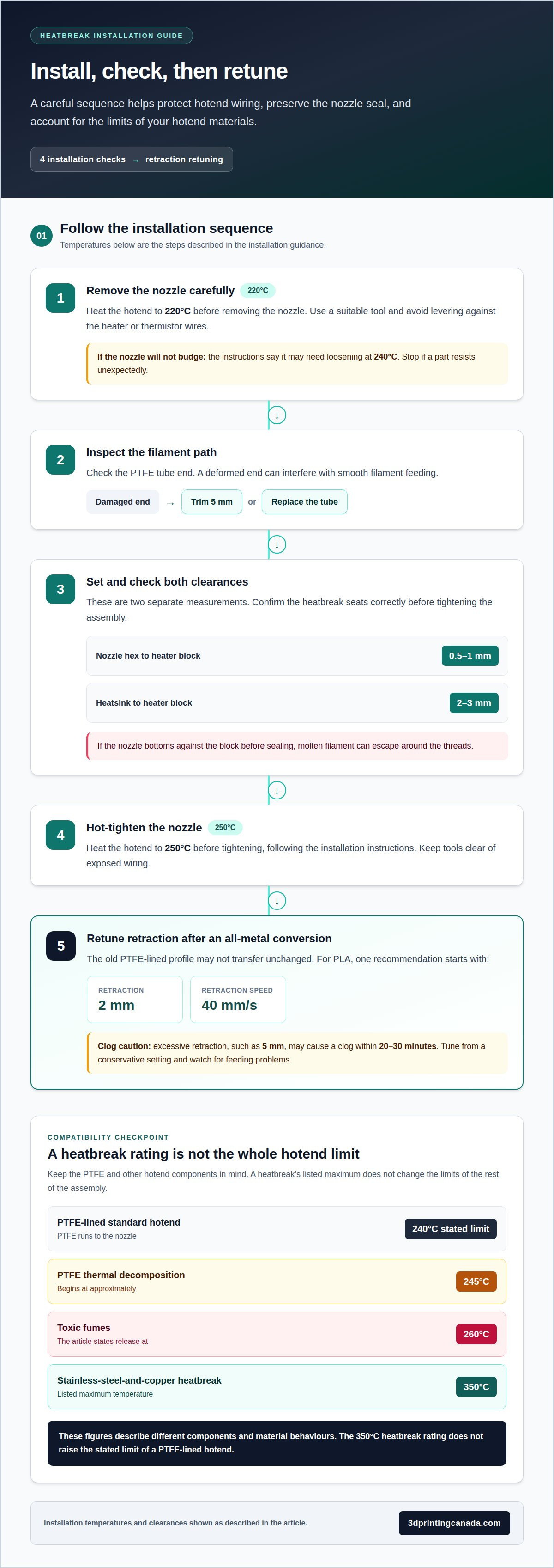
Follow the hotend’s assembly sequence rather than forcing parts together cold. Installation instructions recommend heating the hotend to 220°C before removing the nozzle. If it will not budge, the nozzle may need loosening at 240°C. These temperatures apply to the removal steps described, not as universal settings for every printer or heatbreak.
During assembly, preserve the clearances that let the nozzle seal against the heat break. The instructions call for a 0.5-1 mm gap between the nozzle hex and heater block, and a 2-3 mm gap between the heatsink and heater block. These are separate measurements. A nozzle that bottoms against the block before sealing can allow molten filament to escape around the threads.
- Remove the nozzle carefully. Heat the hotend to 220°C, then use a suitable tool without levering against heater or thermistor wires. If the nozzle will not move, the instructions say it may need loosening at 240°C.
- Inspect the filament path. A deformed PTFE tube end can interfere with smooth feeding. The installation guidance recommends trimming 5 mm from the damaged end or replacing the tube.
- Set the clearances. Keep the specified 0.5-1 mm nozzle-hex gap and 2-3 mm heatsink-to-block gap. Confirm the heat break seats correctly before tightening the assembly.
- Hot-tighten the nozzle. Heat the hotend to 250°C before tightening, following the installation instructions. Keep tools clear of exposed wiring during this step.
Material choice also affects safe use. PTFE begins thermal decomposition at approximately 245°C, and standard hotends with PTFE running to the nozzle have a stated limit of 240°C. The stated release of toxic fumes at 260°C makes it especially important not to treat a PTFE-lined hotend like an all-metal setup. A stainless-steel-and-copper heat break is listed to 350°C, but that rating does not change the limits of other hotend components.
Retraction settings need adjustment after an all-metal conversion because softened filament can travel into a cooler section and stick. For PLA, one recommendation starts at 2 mm retraction and 40 mm/s; excessive retraction, such as 5 mm, may cause a clog within 20-30 minutes. Tune from a conservative setting and watch for feeding problems rather than assuming the old PTFE-lined profile will transfer unchanged.
Heat transfer, heat creep, and filament friction
A heatbreak keeps the upper filament path cooler than the melt zone. Heat travelling upward can soften filament too early, increasing contact with the tube and friction. That resistance can interrupt feeding or cause the extruder gear to grind. Bi-metal heatbreak thermal barrier performance is reflected in extrusion behaviour, not just the material label.
Ender-3 extrusion tests illustrate the difference under a particular setup. The standard Bowden arrangement began showing a substantial extrusion drop and feeder-gear grinding at 10 mm³/s. A generic bi-metal heatbreak began causing severe feeder grinding at around 15 mm³/s. These figures compare tested configurations, not guaranteed limits for every Ender-3, filament, or hotend. Nozzle condition, cooling, temperature, and filament path also affect the result.
A separate Ender-3 test examined a small change to the Bowden path. Moving the tube upward by 1 mm caused the extrusion-test drop from grinding to begin at 7 mm³/s. The result shows how contact and alignment can influence friction alongside heat transfer. A heatbreak can restrict upward conduction, but a poorly aligned tube or increased resistance elsewhere can still limit extrusion.
How can heatbreak thermal performance be tested or measured? Compare otherwise identical hotend setups using the same filament, temperature, cooling and extrusion rate. Record when flow drops or the feeder gear grinds, then compare the results across heatbreaks.
For a practical comparison, an extrusion test can progress from 1 mm³/s to 20 mm³/s, recording where extrusion becomes inconsistent. Keep the printer, filament, and test conditions constant between runs. A Benchy printed at 0.16 mm layer height offers a second, more familiar check: typical flow rates ranged from about 2 to 4.5 mm³/s, depending on the feature. That lower-flow print can reveal everyday symptoms, while a stepped extrusion test pushes the system harder.
- Watch the feeder. Grinding or skipped feeding marks resistance, as seen in the Ender-3 tests.
- Track flow. Note the rate where extrusion starts dropping, not only whether a print completes.
- Compare print features. Benchy walls and smaller details can expose inconsistent flow at different demands.
- Keep variables steady. Use the same filament and printer settings so the heatbreak remains the main change.
To compare bi-metal heatbreak thermal barrier performance, assess both extrusion-test results and actual print quality. A higher flow threshold in one test does not mean every filament will behave the same way. Use the filaments you plan to print, then check for smooth feeding and consistent extrusion across the intended range.
How does bi-metal heatbreak performance compare with all-metal and PTFE-lined heatbreaks?
These three designs handle heat along the filament path differently. A PTFE-lined hotend has a low-friction tube extending towards the nozzle, while an all-metal design uses metal throughout the path. A bi-metal heatbreak also has a metal filament path, but combines materials to manage heat transfer across the break. The best fit depends on printing temperature, filament and hotend construction.
PTFE-lined designs can suit PLA printing because the tube provides a smooth surface through the upper hotend.
All-metal heatbreaks remove PTFE from the path near the nozzle, making them useful when the filament and hotend require higher temperatures. Contact between metal and filament can create more friction than a smooth PTFE tube, particularly if softened filament travels too far into the cooler section. This can affect retraction behaviour, so an existing PLA profile may need adjustment after switching from a PTFE-lined setup.
A bi-metal heatbreak combines an all-metal filament path with a more controlled thermal gradient. Its materials are selected to restrict heat travelling upward while transferring heat near the heater block. This can help reduce heat creep without a PTFE liner near the nozzle. Results still depend on geometry, assembly, cooling and how the filament behaves in that printer.
- PTFE-lined: A smooth tube supports low-friction feeding, but the stated 240°C hotend limit constrains use.
- All-metal: A metal path avoids a PTFE tube at the nozzle, but can require careful retraction tuning.
- Bi-metal: Different metal sections manage heat flow, with performance shaped by their design and fit.
For example, a printer used mainly for PLA at modest temperatures may benefit from the straightforward feeding of a PTFE-lined path. A project requiring temperatures beyond the hotend’s stated limit needs a different hotend configuration, not simply a higher slicer setting. An all-metal or bi-metal design may suit that change, provided the printer’s other components and the filament also support the intended temperature.
Compare the entire filament route, not just the heatbreak. A PTFE tube ending above the nozzle differs from one that reaches the nozzle, and its placement affects the relevant thermal limit. A bi-metal part also needs to match the hotend and seat correctly to provide its intended heat path. Check the installed hotend design before choosing a category.
Choose PTFE-lined construction for compatible lower-temperature use. Consider all-metal or bi-metal construction when the printing temperature requires a metal path. Between those options, choose a bi-metal design when its documented geometry and material pairing suit your hotend’s thermal needs.
What temperature range can a bi-metal heatbreak safely handle?
There isn’t one temperature ceiling for every bi-metal heatbreak. The listed maximum depends on its material pairing: titanium-alloy heatbreaks are listed to 300°C, while stainless-steel-and-copper designs are listed to 350°C. Treat these as component ratings, not a promise that an entire hotend or printer can operate at those temperatures.
The distinction matters because the heatbreak is only one part of the hotend. The heater block, nozzle, thermistor, wiring, and control system also experience heat. A 350°C-rated heatbreak cannot raise the temperature limits of other components. The usable range is governed by the lowest-rated part in the assembled system, along with the requirements of the filament being printed.
For example, a stainless-steel-and-copper heatbreak may have a higher listed maximum than a titanium-alloy design. That difference matters only if the rest of the hotend supports the intended temperature. A printer set up for lower-temperature PLA printing gains no practical advantage just from installing a higher-rated heatbreak. Match the rating to the material and hotend instead of choosing the largest number.
Use this sequence to assess a target temperature:
- Identify the heatbreak material. The listed maximum is 300°C for titanium alloy and 350°C for stainless steel and copper.
- Consider the complete hotend. The heater, sensor, wiring, nozzle, and heatbreak must all suit the planned temperature.
- Match the filament. The filament’s printing requirements determine the temperature the hotend needs to reach.
- Respect the weakest component. Set the operating ceiling by the lowest temperature rating in the complete assembly.
A PTFE-lined filament path is a separate constraint, even when paired with a high-rated heatbreak. Standard hotends with PTFE running to the nozzle have a stated limit of 240°C. Check the path design before selecting a target, since a heatbreak’s material rating does not override the PTFE limit.
Temperature also affects the printing environment. For printing above 240°C, the guidance recommends a well-ventilated area or an enclosure with active filtration. This is a practical consideration when choosing whether a higher-temperature setup fits the workspace, not a substitute for checking component ratings.
- Choose titanium alloy when its listed 300°C maximum fits the intended setup.
- Consider stainless steel and copper when the listed 350°C maximum matches the complete hotend’s requirements.
- Reassess PTFE-lined designs against their stated 240°C limit before planning hotter printing.
Need help diagnosing a hotend issue before choosing a heatbreak? Get help with a 3D printer repair and make the temperature limit a clear part of the diagnosis.
3D Printing Canada
3D Printing Canada can help you connect heatbreak choices with the wider needs of your printer, filament, and hotend. If inconsistent extrusion, clogs, or temperature issues continue after an upgrade, its 3D Printer Repair Services can help address printer hardware problems. For setup decisions, consider how the heatbreak works with the filament and compatible accessories you use.
Turn to 3D Printing Canada when you need repair support or help choosing related 3D printing supplies. Share what your printer is doing and what materials you plan to print, then discuss a practical next step.
Contact 3D Printing Canada to talk through your printer questions.
Make your next hotend decision with confidence
Let your printer’s needs guide the next step: the materials you print, the hotend’s construction and the extrusion behaviour you want to improve. Bi-metal heatbreak thermal barrier performance depends on how these elements work together, not on a rating in isolation.
If you’re planning a broader setup change, connect the heatbreak choice to compatible accessories and materials. 3D Printing Canada offers Bambu Lab Accessories and 3D Printeda, alongside 3D Printer Repair Services for hardware issues that affect printing. That support can help you move from comparing designs to addressing the practical needs of your printer.
Bring your printer questions and intended use into the conversation. Contact 3D Printing Canada today to discuss a sensible next step for your setup.
When your hotend, filament and printing goals are a good match, you can make a more informed upgrade and get back to creating.
Frequently Asked Questions
Should you do this upgrade?
Upgrade if your current hotend’s heatbreak limits the materials you can print or the extrusion behaviour you need. For example, a printer intended for higher-temperature filament may need a metal filament path rather than a PTFE-lined one. First identify the installed hotend and its connection style. If prints feed consistently and stay within the hotend’s limits, replacing the heatbreak alone may not solve other print problems.
How does a bi-metal heatbreak reduce heat transfer in a 3D printer hotend?
A bi-metal design joins materials with different thermal properties to create a temperature gradient between the heater block and the cooler upper hotend. The heatbreak’s geometry also affects how readily heat travels along that path. This controlled transition helps keep filament from softening too far above the nozzle’s melt zone. Results depend on the complete hotend, including its assembly and cooling, not just the heatbreak material.
What are the thermal conductivity values of common bi-metal heatbreak materials such as copper, titanium, and stainless steel?
Thermal conductivity varies with the specific alloy and its temperature, so a material name alone does not give an exact value. Copper generally conducts heat more readily than titanium or stainless steel, which is why these materials can serve different roles in a heatbreak. Compare the alloy and construction details of the part you’re considering. The assembled geometry also affects heat flow, beyond conductivity values alone.
How much does a bi-metal heatbreak reduce heat creep and clogging?
No single reduction applies across all printers, materials and hotend setups. Heat creep and clogs also depend on cooling, filament condition, retraction and heatbreak fit. After an upgrade, look for changes such as fewer feeding interruptions under the same print conditions. If clogs persist, treat them as a diagnostic clue: the cause may lie elsewhere in the filament path.
Which bi-metal heatbreak designs are compatible with popular 3D printer hotends?
Compatibility depends on the hotend’s dimensions, threads, and filament-path design, so there isn’t a universal bi-metal replacement. Some early Artillery Sidewinder X1 and Genius printers use a RepRap 1.75 threaded heatbreak; smooth variants have a different connection style. MK10 hotends also require a heatbreak designed to fit their assembly. Match the part’s stated dimensions and connection to the installed hotend before replacing anything.
What are the installation steps and thermal paste recommendations for a bi-metal heatbreak?
First identify the hotend and follow its assembly instructions. Carefully remove the nozzle and old heatbreak, keeping tools clear of heater and thermistor wires. Inspect the filament path, seat the replacement correctly, then reassemble and secure the nozzle according to the specified procedure. Use thermal paste only if the heatbreak or hotend instructions call for it, and only on the designated interface, never in the filament path.
What problems can occur with bi-metal heatbreaks, such as leaks, clogs, or filament jams?
Poor seating or an incorrect fit can cause filament to leak around the hotend joint. Heat creep, excess friction or a damaged filament path can contribute to clogs and jams. Since the symptoms can look similar, note where residue appears and whether the extruder still feeds filament smoothly. A jam that persists after clearing the nozzle may indicate resistance higher in the path or an assembly issue.