
A gyroid is a continuous, wave-like infill pattern that distributes structure through a part in multiple directions. It can maintain shear strength and resistance at densities as low as 10%, but it isn’t automatically the top performer: hexagonal infill has the highest strength-to-weight ratio among the patterns compared here. That’s the key to an infill-pattern strength-to-weight-ratio comparison: the best choice depends on the balance of strength, material use and print time you need.
It’s easy to assume that more infill, or a more intricate pattern, means a stronger part. But pattern geometry, infill density and load direction all affect performance. This guide compares common patterns by strength-to-weight ratio, material use and print time, including gyroid, triangle, grid and honeycomb. You’ll learn which trade-offs matter for prototypes and functional parts, so you can choose an infill pattern based on what the print needs to do, not just how it looks in the slicer.
Key Takeaways
- Choose infill based on the direction and type of force the part will face; tensile and bending tests can favour different patterns.
- A rectangular-and-triangular combination improved strength-to-weight ratio by 27.74% in the study while using less material and reducing build time.
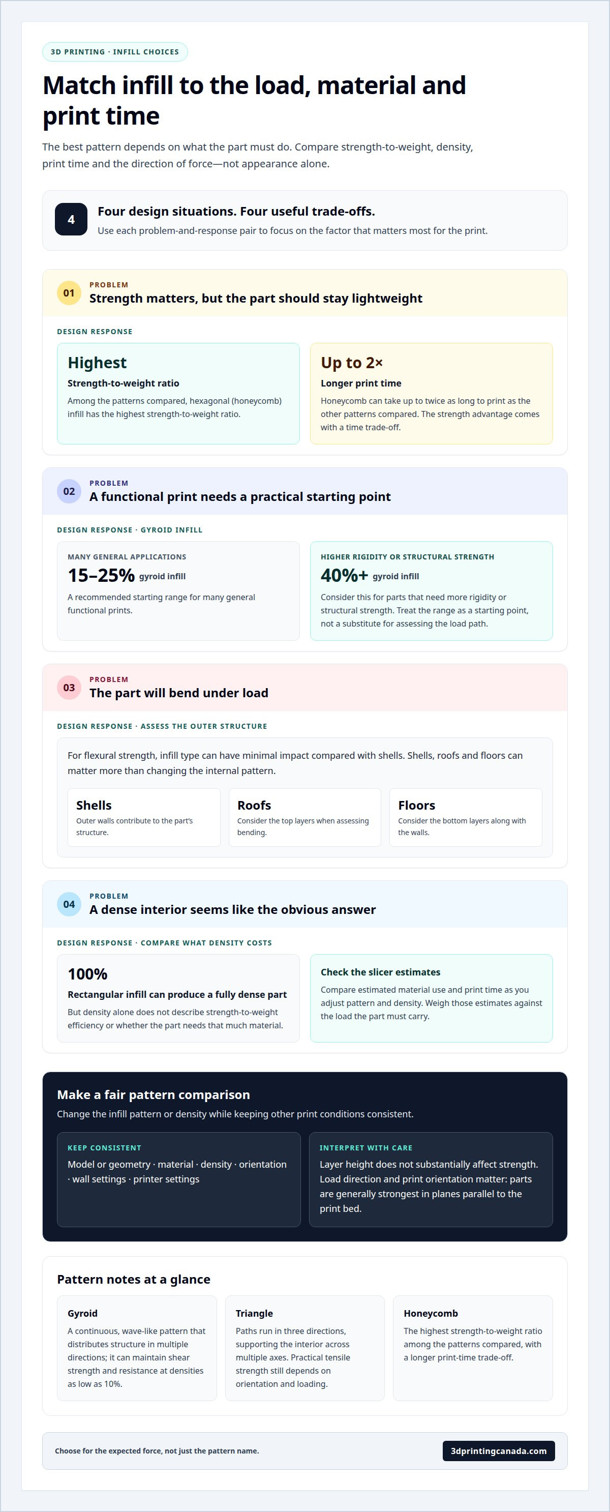
- Honeycomb can take up to twice as long to print as the other patterns compared, so factor production time into your choice.
- For flexural strength, shells, roofs and floors can matter more than infill pattern, making the part’s outer structure worth considering.
- Match density to the job: prototypes and functional parts may need different balances of rigidity, material use and print time.
Hexagonal infill strength-to-weight ratio and print time
Hexagonal, or honeycomb, infill has the highest strength-to-weight ratio among the patterns compared here. That advantage comes with a trade-off: honeycomb can take up to twice as long to print as the options described earlier, making it the slowest pattern discussed. For a lightweight part where strength matters, the extra time may be worthwhile. For a prototype on a tight schedule, another pattern may be more practical.
How do infill pattern, layer orientation, and wall count affect 3D printed part strength? The pattern changes how internal material supports a load; orientation determines how the printed layers meet that force, and more shells, roofs, or floors can affect flexural strength more than infill does. Deposition-based parts are generally strongest in planes parallel to the print bed, so consider the load direction before choosing a pattern or print orientation.
Rectangular infill offers a different density option: it can produce a 100% dense 3D-printed part. That does not make it the automatic choice for every component, because density alone doesn’t describe strength-to-weight efficiency. Compare the material used with the load the part must carry. In a slicer, review the estimated material and print time as you adjust the infill pattern and density; the result helps reveal whether a dense interior is worth the added build time for your design.
Triangle infill lays paths in three directions, supporting the interior across multiple axes. Although triangles are often considered a strong shape, practical tensile strength depends on the part’s orientation and how it is loaded. A visually braced interior does not necessarily print faster. Toolpath length, direction changes and printer settings affect print time, while the comparisons here identify honeycomb as the slowest pattern discussed.
In your slicer, compare patterns using the same model, material, density and printer settings. Changing several variables at once makes it difficult to tell whether a result comes from the pattern or another setting. Layer height does not substantially affect strength, while shells, roofs and floors can have a greater effect on flexural strength. On a bracket loaded from above, for example, the outer walls and top and bottom layers may matter more than changing the internal geometry.
Print orientation is a manufacturing decision, not just a way to fit a model on the bed. Position the part so the expected force acts in the plane where deposited material is generally strongest, and check whether the outer walls support bending loads. Hexagonal infill can be efficient for strength, but it takes longer to print. Rectangular and triangular paths offer different trade-offs, so consider the slicer’s time and material estimates alongside the load direction.
Applications in prototypes and mechanical components
For a prototype, infill balances internal support against material use and build time. A display mock-up may need only enough structure to hold its shape, while a working bracket must withstand force at its mounting points. Choose the pattern for the part’s expected loads, not its appearance alone. In FDM printing, deposited material forms layers, and their orientation affects how the part responds to force.
Does infill pattern performance vary between PLA, PETG and ABS? Yes. Material and printing conditions affect a finished part’s mechanical properties, so a pattern may perform differently across these materials. To isolate the effect of infill, compare prints with the same geometry, density, orientation and wall settings.
For functional prints, gyroid infill is recommended at 15-25% for many general applications. Parts that need higher rigidity or structural strength may call for gyroid at 40% or more. Treat those ranges as starting points for the design task, not a substitute for considering the load path. A prototype enclosure and a load-bearing fixture, for example, do not need identical internal structures.
For mechanical components, consider bending carefully. Infill type has minimal impact on flexural strength compared with shells, so adding internal density may help less than strengthening the part’s outer structure. A long printed arm that bends under load illustrates the difference: its walls, roofs and floors contribute to resistance, while infill supports the interior. Assess both in the slicer rather than relying on the pattern name.
FDM deposition also creates directional behaviour. Parts are generally strongest in planes parallel to the print bed, so orientation matters when a prototype will be pulled, bent or compressed. Position the model to suit the expected force, then consider how the infill supports the load through the interior. This matters especially for components with a clear mounting face or predictable stress direction.
Keep comparisons controlled. Print test versions with the same material, model, orientation and wall settings, then change the infill pattern or density. This makes results easier to interpret when developing a mechanical component. Layer height does not substantially affect strength, while shells, roofs and floors can matter more than infill changes for bending performance. Use these factors to decide what to adjust first, and add material where the structure needs support.
Rectilinear, triangular, rectangular and honeycomb infills
Grid, Triangle, Wiggle and honeycomb route filament along different paths, changing how they support a printed part. Comparing test results helps match infill geometry to the load and build priorities.
Comparing Grid, Triangle, Wiggle, and Honeycomb
Grid lays paths in two directions, with the second rotated by 90°, while Triangle builds paths in three directions. Wiggle uses a winding path, and honeycomb forms connected hexagonal cells. In tensile testing, Wiggle had the highest strength-to-weight ratio among the tested samples. In bending tests, Triangle ranked highest, about 39% above Grid. Those different results show why the load type matters.
The tensile comparison tested five patterns in the samples’ middle layers: Grid, Triangle, Wiggle, Fast Honeycomb and Full Honeycomb. Honeycomb uses approximately 25% more material than other patterns, making its geometry a trade-off rather than a direct efficiency win. For a bracket pulled along one axis, tensile results may be more relevant than a bending comparison; a panel that flexes calls for the latter.
Rectangular and Triangular Combinations
A rectangular-and-triangular combination joins the two geometries to balance internal support with material use. In the study, this combination increased the strength-to-weight ratio by 27.74%, saved 10.58% of material and reduced build time by 4.08%. These figures make the hybrid worth considering when both efficiency and production time matter.
Rectangular infill can produce a 100% dense part, while the combined pattern’s reported savings show that a fully solid interior isn’t the only route to strength. Compare the hybrid with a single pattern using the same model and settings. That keeps changes in material and build time tied to the pattern choice, not to a different print setup.
Triangle Infill Truss Behaviour
Triangle infill behaves like a repeated truss: connected triangular paths provide support in three directions. This geometry can help distribute loads through the interior, which matters for parts exposed to bending or force from multiple directions. Triangle’s strong bending result, about 39% above Grid, illustrates its potential in that test context, not a universal ranking for every load.
Pattern selection also depends on force direction. Gyroid provides strength in all directions, while Grid’s crossed paths and Triangle’s three-direction structure support loads differently. Tri-hexagon is another pattern to compare in a slicer, but its name alone does not establish its performance. Match the pattern to the expected load, then weigh material use and print paths against relevant tensile or bending results.
Strength-to-weight and density-to-strength efficiency
Which infill patterns use the least filament while maintaining adequate strength? Adaptive cubic uses approximately one-quarter less material than rectilinear infill, while gyroid can maintain shear strength and resistance at densities as low as 10%. The right balance comes from matching internal support to the part’s load, rather than maximizing density by default.
Density and Mechanical Performance
Infill density describes how much of a part’s interior contains printed material, influencing its weight and mechanical performance. Infill density varies by design, with higher density meaning more of the part’s interior is filled. Increasing density adds internal material, but strength-to-weight efficiency asks whether that added weight delivers useful performance. For a lightweight prototype, compare the strength required with the load it will face before increasing density.
Density and Internal Support
Infill creates internal support beneath the outer walls and top surfaces, while density affects how much material forms that support. At 100% infill, the printed part is completely solid, but that maximum density is not automatically the most efficient choice. A part that needs support beneath a broad top surface has different priorities from a thin component loaded in shear. Consider the geometry and force direction alongside density.
A printed part’s mechanical properties depend on the whole structure, not just its infill. Shells, roofs and floors can affect flexural strength more than infill does. For a rectangular beam under bending load, strengthening the outer structure may improve resistance more effectively than adding material throughout the core. Balance the shell and infill to suit the part’s job.
Adaptive Cubic Density
Adaptive cubic varies its internal structure to place support where the model needs it, rather than using uniform rectilinear infill throughout. It uses approximately one-quarter less material than rectilinear, which can improve density-to-strength efficiency when saving filament matters. This comparison can help when planning a lightweight component, but the design still needs enough support for its expected loads and surfaces.
Gyroid offers another density-efficient option. It can maintain shear strength and resistance at densities as low as 10%, making it relevant for parts where those properties matter. That does not mean 10% suits every application: a component exposed to bending, compression or concentrated loads needs internal support suited to those forces. Use the load case to guide pattern and density choices.
For a practical comparison, keep the model and material constant, then test patterns at the same infill density. Review the slicer’s material estimate alongside the part’s mechanical requirements. This separates the effect of geometry from added density and helps show whether adaptive cubic, gyroid or rectilinear offers a useful balance for the design.
Strength-to-weight ratios of individual and combined infill patterns
Pattern rankings depend on the test: tensile and bending loads can produce different winners. For lightweight parts, compare load conditions, material use and print time together.
Equal-Percentage Strength and Weight Results
Equal-percentage comparisons hold infill density constant, helping show how pattern geometry changes strength and weight. Stress-strain comparisons cover 30%, 60% and 90% infill, while fatigue curves compare three patterns at those same densities. Tensile-test strength-to-weight results can vary by infill pattern. Triangle led the bending samples, with a result about 39% above Grid.
Tensile and bending results are not interchangeable: tensile strength measures resistance to pulling, while bending tests assess flexural behaviour. Results also depend on the test load, polymer and print parameters. For a part pulled along its length, tensile results are more relevant; for a beam that flexes, compare bending results.
Lightweight Functional Part Patterns
The best pattern for a lightweight functional print depends on its job, not a universal ranking. Gyroid is recommended at 15-25% infill for many functional prints, while parts needing greater rigidity or structural strength may use 40% or more. Its continuous geometry provides strength in all directions, making it a useful option when loads can come from different directions.
When choosing a strong, lightweight print, start with the force direction and material. Then compare gyroid with the tested patterns: Wiggle led in tensile strength-to-weight, while Triangle led in bending. These results provide practical guidance, but the right choice depends on the component’s actual use and slicer settings.
Combined patterns can shift the balance further. A rectangular-and-triangular combination increased strength-to-weight ratio by 27.74%, saved 10.58% of material and reduced build time by 4.08% in the study. That makes it a compelling candidate where reduced plastic use and shorter manufacturing time matter alongside strength.
Use the figures as comparisons, not guarantees across every printed shape. The fatigue results at 30%, 60% and 90% show why density should stay consistent when evaluating geometry. For a functional component, match the test type to the expected load, then compare the material and time estimates for each pattern. This keeps the decision grounded in the part’s requirements.
Ready to apply these comparisons to your next print? Explore 3D printing resources as you refine the pattern and parameters for your design.
3D Printing Canada: Bambu Lab Accessories
3D Printing Canada is a practical next step when you’re ready to apply these pattern comparisons to your own prints. The right infill works alongside dependable printer operation, suitable materials and consistent setup. If equipment issues interrupt that process, 3D Printing Canada offers 3D Printer Repair Services. Bambu Lab Accessories can also support your printer setup, while 3D scanners help with capturing physical objects for digital workflows.
Use the test results to narrow your pattern choice, then consider whether your equipment or setup needs attention before printing a functional part. That’s especially useful when comparing prototypes with different loads or refining a design for repeat printing. For help with printer repairs or relevant printing equipment, contact 3D Printing Canada.
Put your next print to the test
Let the part’s real job guide your design decision. Before printing, identify where it will be supported, how force will reach it and what failure would look like. Then use your infill patterns strength-to-weight ratio comparison to choose a sensible starting point, not as a substitute for testing the finished component.
A useful next step is to print a small test piece that reflects the part’s geometry and intended use. Keep the material and slicer settings consistent as you compare patterns, and record how the results change. This gives you practical evidence to refine the design instead of relying on a pattern name alone.
If you’re preparing a print and need help with your equipment or setup, contact 3D Printing Canada. Keep experimenting, learn from each test, and build the version that works for your project.
Frequently Asked Questions
How is strength-to-weight ratio measured for 3D printing infill patterns?
Divide the load a printed sample withstands by its mass to compare strength per unit of weight. For a fair comparison, keep the sample shape, polymer, infill density and print settings consistent, then test every pattern in the same direction. Tensile and bending tests measure different responses, so record the test type with each result. The ratio helps rank samples, but the intended part’s load should guide pattern selection.
Which 3D printer infill pattern has the highest strength-to-weight ratio?
Hexagonal infill has the highest strength-to-weight ratio among the patterns discussed, but the test type changes the ranking. Wiggle ranked highest in the tensile samples, while Triangle led in bending. Treat each result as specific to its test and sample conditions, not as a universal winner. For a lightweight part, match the comparison to its main demand: pulling, bending or another load.
How do gyroid, cubic, honeycomb, grid, and triangle infill compare?
Gyroid distributes strength in all directions, while Grid crosses paths in two directions and Triangle uses three. Honeycomb’s cell structure can require more material than other patterns, while adaptive cubic can use less than rectilinear infill. These geometries are not interchangeable: a part loaded from changing directions may benefit from a different structure than one pulled along a known axis. Compare equivalent prints under the relevant load test.
How does infill percentage affect part strength and weight?
Increasing infill percentage adds material inside a part, generally increasing its weight and changing how its interior supports loads. The strength gain depends on the pattern, outer walls and force direction, so greater density does not guarantee a proportional improvement in useful performance. For a lightweight design, compare load response with mass, and consider whether strengthening the shell would better address the failure point.
Which infill pattern performs best in tensile, compression, and bending tests?
Wiggle led in the tensile samples, while Triangle produced the strongest bending result among the tested patterns. These results do not establish one winner across tensile, compression and bending. For compression, compare samples tested under compressive loading and consider how the part’s shape carries force. A pattern’s performance under pulling or bending cannot predict its compression performance, so choose evidence that matches the component’s actual load.