
A visible Z seam isn’t a slicer failure; it marks where each layer’s perimeter starts and ends. Seam hiding alignment techniques in a slicer control where those start points land, letting you place the seam at the back, along an edge, or distribute it across the surface. You can often make the seam less noticeable, though its visibility depends on the model and print settings.
A line, ridge, or small bumps on a print can come from the way each layer starts and stops. The best approach depends on the model: a deliberate seam may suit a part with a clear back, while scattered starts can work better on an organic shape.
This guide explains how common seam alignment modes behave, when to use each, and how to reduce extrusion variation at layer starts. It also covers practical ways to test settings, orient a model, and decide whether post-processing could help. Change one setting at a time, then assess the result on a small test print before applying it to a larger project.
Key Takeaways
- Choose seam placement to suit the model: a rear seam can keep a clear front cleaner, while random placement spreads marks across the surface.
- Match alignment mode to the part’s purpose and shape; what works for an internal component may not suit a decorative cylinder.
- Use model orientation, wall-printing order, and small design details to make seams less noticeable.
- Fine-tune retraction, wiping, and coasting to reduce blobs or rough starts, then assess changes on a small test print.
- For boxy parts, placing seams along corners or edges can help them blend into the geometry.
Aligned seam placement
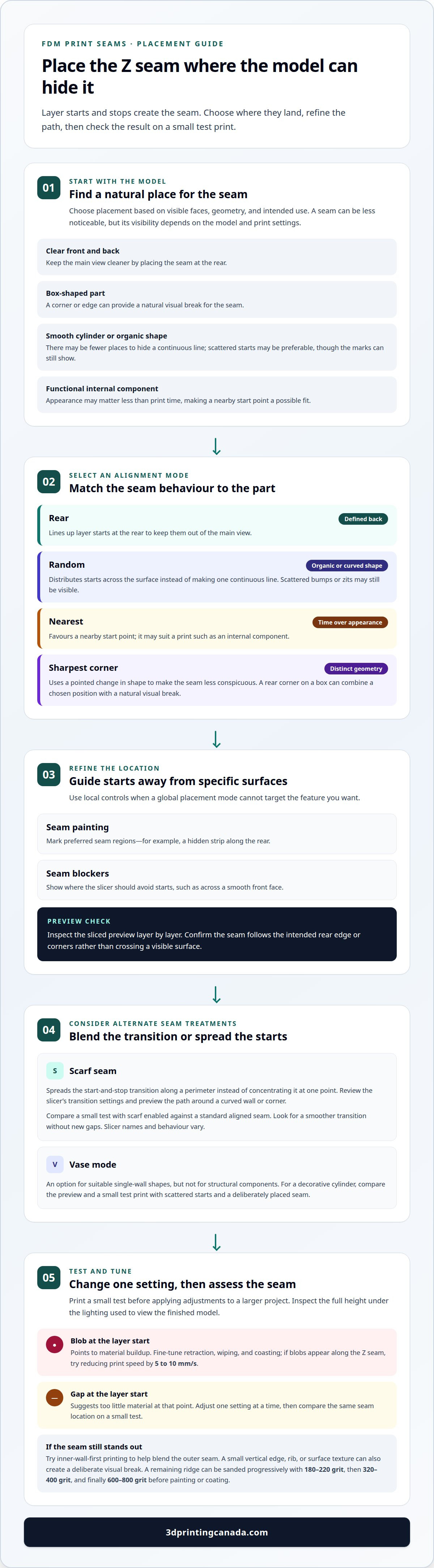
Seam alignment controls where each perimeter begins and ends, creating a vertical line of start points called the Z seam. Choose its position based on the model’s visible faces, geometry, and intended use.
Rear, Random, Nearest, and Sharpest-Corner Placement
These four placement options determine whether layer starts line up at the rear, scatter across the surface, favour a nearby start point, or sit at a corner. Rear placement suits a model with a clear front and back: align the seam at the rear to keep it out of the main view. Random placement distributes starts across the surface, replacing one continuous line with scattered bumps or zits.
Nearest placement favours a nearby start point, which can suit a print where time matters more than appearance, such as an internal component. Sharpest-corner placement uses a pointed change in geometry to make the seam less conspicuous. On a box-shaped part, a rear corner can provide both a chosen seam position and a natural visual break.
Scarf Seam Settings
A scarf seam spreads the start-and-stop transition along a perimeter instead of concentrating it at one point. This can reduce a distinct seam mark by blending the extrusion change into the surrounding wall.
If your slicer offers scarf controls, enable the feature and review its transition settings before slicing. Names and behaviour vary between slicers, so use the preview to see how the path changes around a curved wall or corner. Compare a small test print with scarf enabled to one with a standard aligned seam; check for a smoother transition without new gaps.
Seam Painting and Blockers
Seam painting lets you mark preferred seam regions on the model, while seam blockers show where the slicer should avoid placing starts. Paint a hidden strip along the rear to guide the seam, or add a blocker across a smooth front face you want to keep clean.
After marking the model, inspect the sliced preview layer by layer. Confirm that the seam follows the intended corners or rear edge rather than crossing a visible surface. Painting and blockers provide local control when a global rear, random, or nearest setting can’t target a specific feature.
For cylindrical or organic models, random placement can distribute the seam instead of creating one prominent line, though scattered marks may still show. Vase mode is another option for suitable single-wall shapes, but it isn’t suitable for structural components. For a decorative cylinder, compare the preview and a small test print before choosing between scattered marks and one deliberately placed seam.
Choose efficiently by identifying the display face, selecting a global placement mode, and refining specific areas with painting or blockers. For a functional internal part, nearest placement may suit your priorities; for a display model with a defined back, rear placement offers more control.
FDM print seam formation and visibility
An FDM seam is the line formed where the nozzle starts and stops each layer’s outer perimeter. Repeated start points can create a visible ridge, gap, or bump, even when the rest of the surface looks smooth. Consumer-grade FFF printing can make the seam less noticeable, but it can’t eliminate it entirely.
Filament colour affects how easily a seam catches the eye because colour and sheen change how light reflects off the surface. A glossy, dark model may show a ridge differently from a matte, light-coloured one. Test with the filament you plan to use: a setting that improves one colour’s appearance may look different with another.
Model geometry determines where a seam can blend in. On a box, a vertical corner can disguise the line; on a smooth cylinder, the uninterrupted surface offers fewer places to hide it. A changing curve or overhang can also draw attention to a seam, especially if layer starts form a ridge across a visible face. Orient the model to protect its best-looking surface.
To reduce seam visibility, combine placement with a controlled test rather than changing several settings at once. Try inner-wall-first printing to help blend the outer seam, then reduce print speed by 5 to 10 mm/s if blobs appear along the Z seam. Add a small vertical edge, rib, or surface texture in the design when the seam needs a deliberate visual break. Print a small test after each adjustment and inspect its full height under the lighting used to view the finished model.
For PLA, PETG, and ABS, start with seam placement and extrusion tuning; material-specific smoothing is a separate finishing choice. Specialized smoothing agents are designed for PLA, while acetone vapour smoothing is used for ABS. Dichloromethane is toxic, so smoothing PETG with it requires good airflow and safety gear.
After changing seam settings, troubleshoot by matching the defect to the layer start: a blob points to material buildup, while a gap suggests too little material at that point. Adjust one setting, then print a small test and compare the same seam location. For a ridge that remains after printing, start sanding with 180-220 grit, move to 320-400 grit, and use 600-800 grit for a uniform finish before painting or coating.
If blobs or gaps continue across test prints despite slicer adjustments, the printer may need attention beyond seam placement. 3D Printer Repair Services can address hardware issues that interfere with consistent printing.
Staggered inner seams
Staggered inner seams put layer starts in less visible positions instead of forming one obvious line. Combine this approach with model orientation and existing features to keep the seam away from the display face.
Layer Start-and-Stop Points
A layer start-and-stop point is where the nozzle begins and ends an outer perimeter, leaving a small mark that can repeat vertically. These marks form the seam across successive layers. On a smooth enclosure, repeated starts can create a noticeable line; shifting their position can move it away from the main viewing angle.
Follow the nozzle path around the model in the slicer preview, noting where each perimeter begins. This reveals whether the seam crosses a broad surface or sits beside a moulded feature. A scarf seam changes how the transition is distributed, but placement still matters when the model has a clearly visible front.
Seams Along Corners and Edges
Corner or edge placement puts the seam where a change in geometry may make it less visible. On a boxy case, align it with a rear vertical corner rather than the centre of the front panel.
Choose an edge based on how the finished part will be viewed, not just the slicer’s default orientation. If the model has a front, back, and side, rotate it before slicing so the preferred seam position falls along a back corner. A crisp edge creates a natural visual break; a broad, uninterrupted face does not.
Staggered Interior Wall Seams
Staggered interior wall seams place inner-wall starts away from the outer seam’s vertical line. This prevents seam marks from stacking directly behind one another across the wall structure.
For a box-shaped print, inspect the interior and exterior paths in the preview. Keep the outer seam near a hidden corner, then use staggered starts for inner walls if the slicer offers that control. Make sure shifting the interior seams doesn’t pull the outer seam onto a visible surface. Review the full layer sequence before printing.
Model features can offer better seam positions than a flat face. A vertical rib, narrow groove, or sharp transition can interrupt the surface and disguise a seam. For example, orient a sculpted object so its back detail faces away from the usual viewing angle, then place the seam beside that detail.
Match seam placement to the model’s geometry and viewing direction. Identify the display face and the edges that already divide the surface. Then set the seam along a rear corner or feature line and inspect the sliced model from the angle people will see it. If the seam crosses an open area, adjust the model’s position or use seam painting to guide it. Change one setting at a time; a small test print shows whether the seam follows the intended path before you print the full model.
Reducing seam-start extrusion variation
Seam-start extrusion variation is a change in material flow where a perimeter begins or ends. The nozzle may leave excess filament as a blob, or too little material may create a gap. Tune retraction, wiping, and coasting separately to see which adjustment affects the seam.
Retraction pulls filament back before a travel move, limiting ooze as the nozzle approaches the next start point. If blobs appear at the seam, increase retraction distance in small steps and inspect the next test print for gaps. Excessive retraction can leave a thin or incomplete start, so stop increasing it if the defect changes from a blob to a gap.
For a direct-drive printer, test a retraction distance of 0.5-1.5 mm to reduce seam blobs. Retraction speed controls how quickly filament moves during that pullback; a useful test range is 25-45 mm/s. Change distance or speed individually, keeping the other setting steady, so the result points to the adjustment that affected extrusion.
Wipe distance is how far the nozzle travels while wiping residual material from the nozzle path. If small zits or rough spots remain at the seam, try a wipe distance of 5-10 mm. The “wipe before external loop” option starts de-retraction slightly inside the external perimeter, rather than at its outer start. That can hide potential over-extrusion beneath the outside surface.
Coasting stops extrusion just before a perimeter ends, using pressure already in the nozzle to finish the path. For a coasting distance setting, try 0.2-0.5 mm as a starting range. If the slicer instead expresses coasting as volume, test 0.1-0.3 mm³. Keep the units straight: distance and volume describe different settings, not interchangeable values. Watch for gaps if coasting removes too much material near the seam.
Test one adjustment at a time on a small print with a clear seam. Keep the model, filament, and other slicer settings unchanged, then compare the same start points. If a blob remains after increasing retraction, review wipe behaviour before changing coasting. If the start becomes sparse, reduce the adjustment that removed too much material. This controlled process helps identify whether the cause is excess pressure, lingering filament, or a depleted start.
Vase mode prints a continuous single-wall path without the usual repeated perimeter starts. It can avoid a conventional seam on suitable decorative forms, but it isn’t suitable for structural components. For other models, use retraction, wipe, and coasting to manage the start while retaining the required wall paths. A cleaner seam comes from matching the setting to the defect, not applying every adjustment at once.
Slicer seam alignment modes
A seam alignment mode tells the slicer where to start each layer’s outer perimeter. Choose one based on surface appearance, model geometry, and print-time priorities. Use seam hiding alignment techniques in slicer software by treating alignment and position as separate decisions: alignment controls how starts are distributed, while position guides where they land.
Rear placement groups starts at the back of a model with a clear front and back. This creates a consistent vertical seam that’s easier to move out of view than scattered marks. For a box with a display face, orient the model so the rear setting directs the seam towards a less visible side. Check the preview to confirm its placement.
Random placement varies the start location between layers instead of building one continuous seam. It can suit cylindrical or organic models, where a single line may stand out, but scattered starts can leave small bumps or zits. Nearest placement favours a nearby start point, making it a practical choice when print time matters more than appearance, such as for an internal component.
Sharpest-corner placement seeks a pointed change in the model’s outline, using its geometry to make the seam less conspicuous. On a boxy part, that may mean putting starts on a corner rather than across a broad wall. Compare the preview from the finished part’s viewing angle. A corner can disguise the seam, while an uninterrupted face offers no natural place for it to blend in.
In Cura, search the settings for Z Seam Alignment and Z Seam Position. Alignment controls how starts are distributed; position guides where they land. To hide the Z seam on a model with a defined back, choose an alignment that keeps starts together, then select a rear position. Inspect the sliced perimeter before printing, since rotating the model changes which side the slicer treats as the back.
No single mode suits every model. A decorative cylinder may suit random placement, while a functional internal part may favour nearest placement. Rear placement can work well on a display model, and a sharp corner can provide a natural visual boundary. Compare seam hiding alignment techniques in slicer previews, then test your choice on a small print before using it on the full model.
The key trade-off is consistency versus dispersion: aligned starts create one seam to conceal, while random starts spread marks across the surface. If a Cura preview repeatedly places the seam somewhere unexpected, get help troubleshooting your printer setup before changing several settings at once.
3D Printing Canada
3D Printing Canada is a practical next step when seam problems persist after you’ve adjusted slicer settings and tested the result. Use the alignment and extrusion checks in this guide to narrow down whether the mark comes from placement or inconsistent printing. If blobs, gaps, or uneven starts continue across different models, 3D Printer Repair Services can address hardware issues affecting print consistency.
For a material change, explore the available filaments and consider how colour and surface finish affect seam visibility. The right choice depends on the model’s geometry, intended use, and the finish you want. Contact 3D Printing Canada to discuss your printer or filament needs.
Make your next print a deliberate test
Before slicing your next model, decide which face matters most. Treat seam hiding alignment techniques in a slicer as part of the design process, not just a last-minute surface adjustment. Save a copy of the profile, change one setting, and compare the result with the original. This gives you a clearer starting point for future prints and helps distinguish slicer choices from hardware or material issues.
When a project calls for a setup change, 3D Printing Canada offers Bambu Lab Accessories and 3D Printeda alongside its other 3D printing offerings. If you’re planning a project or troubleshooting print consistency, get in touch with 3D Printing Canada to discuss the next step. Keep experimenting with one controlled change at a time, and build on what each print teaches you.
Frequently Asked Questions
What Are Seams (Z Seams)?
Z seams are the vertical traces left where successive layers begin or end their outer perimeters. They’re especially easy to spot on a smooth vase or enclosure because the marks line up across the model’s height. The seam’s appearance varies with surface finish and viewing angle. Slicer settings can move or disperse the marks, but consumer FFF printing can’t eliminate them entirely.
What is the seam in FDM 3D printing, and why is it visible?
In FDM printing, the seam is the trace left where the nozzle starts and stops each layer’s perimeter. A small change in extrusion at those transitions can leave a ridge, gap, or bump. Such defects are easier to notice on smooth walls than textured surfaces. For example, a narrow groove can break up a long reflection and make the seam less prominent.
How do seam alignment settings work in popular 3D slicers?
Seam alignment settings tell the slicer where to place perimeter start points when generating toolpaths. Options and labels vary, so inspect the actual path in the layer preview rather than relying on a setting name alone. In Cura, search for Z seam alignment and Z seam position, then preview a model with a clear front to see how those choices affect its outer wall.
What is the difference between aligned, nearest, random, and rear seam placement?
Aligned placement groups layer starts into a consistent seam, while rear placement directs that seam towards the model’s back. Nearest placement favours a nearby start point, which can suit an internal part where appearance is secondary. Random placement varies starts around the model, avoiding one continuous line but potentially leaving scattered marks. Choose based on the model’s shape and the surfaces people will see.
How do retraction, pressure advance, wipe, and coasting settings reduce seam blobs?
Retraction pulls filament back before travel, while wipe moves the nozzle to clear residual material. Coasting ends extrusion before the perimeter finishes, using pressure already in the nozzle. Pressure advance adjusts extrusion to account for pressure changes as the nozzle moves. These controls affect different parts of the start-and-stop transition, so tune them one at a time. Too much retraction or coasting can replace blobs with gaps.
How do print orientation, model geometry, and layer height affect seam visibility?
Orientation changes which face or edge presents the seam to a viewer, while geometry determines whether an edge, recess, or rib can disguise it. Layer height affects the vertical spacing of layer transitions and how the surface looks; it doesn’t relocate the seam. For a display object, orient its best face outward and inspect the sliced preview before choosing a position.
What are the trade-offs of hiding the seam in corners versus using random seam placement?
Placing a seam at a corner gives boxy models one predictable line that can blend with an existing edge. This is less suitable if the corner is prominent or exposed. Random placement avoids a single continuous stripe, which can help on organic forms, but spreads small marks across more of the surface. Choose a corner for controlled concealment, or random placement when scattered texture suits the design.
Which seam hiding techniques work best for PLA, PETG, and ABS?
For PLA, PETG, and ABS, start with seam placement and extrusion tuning, then test changes on a small print. PLA may respond to specialized smoothing agents, while acetone vapour smoothing is used for ABS. Dichloromethane for PETG requires good airflow and safety gear because it is toxic.