
Grid can print quickly, but its crossing lines may create raised spots that a moving nozzle scrapes. If you’re comparing gyroid infill vs grid infill to fix nozzle dragging, Gyroid is often the better first test: its paths avoid in-layer crossings and distribute forces more evenly. Grid can still work well when straight-line stiffness and print speed are priorities.
That scraping sound is frustrating, especially when a print looks fine until the nozzle catches on infill. The pattern may be responsible, but excess material, travel behaviour and printer settings can also reduce clearance. Compare Gyroid and Grid for strength, shear resistance, print time and scraping risk to choose a pattern that fits the part and your printer.
Key Takeaways
- Choose gyroid when multidirectional loads and shear resistance matter; grid favours stiffness along its straight-line directions.
- Grid’s crossing paths can build up at intersections, creating raised spots the nozzle may scrape.
- Compare print time as well as strength: grid can be faster, while gyroid’s curved paths may take longer.
- If scraping continues after adjusting the infill pattern and settings, consider whether a printer hardware issue needs attention.
- Use the decision guide to match the pattern to your part’s loads, desired finish and printer behaviour.
Nozzle collisions and vibration on fast printers
Fast motion can turn small infill height differences into audible nozzle knocks. The risk becomes more noticeable above 250 mm/s and accelerations exceeding 10,000 mm/s², where rapid direction changes make the printer frame and toolhead vibrate. A nozzle crossing a raised line may scrape the surface, while repeated vibration can leave visible marks or disturb a print. These signs point to different causes, so note when the sound occurs: at intersections, during direction changes, or throughout infill travel.
In a reported example, rectilinear infill at 25% density dragged on larger prints. Another PETG print on an Ender 3 V3 KE produced grid scraping during a 12-hour run, with noise beginning around layer 80. As a print grows, accumulated material or a raised crossing can bring the nozzle closer to the infill. A noise that appears only after many layers may therefore differ from vibration heard from the first infill pass.
Resonance is another factor. A high-speed CoreXY printer can vibrate when raised intersections in Grid or Triangle paths meet high acceleration, particularly above 10,000 mm/s². Gyroid removes those in-layer crossings, but its continuous curves can still excite a machine with loose belts or uncalibrated resonance tuning. If loose belts or resonance tuning may be contributing, check belt tension and resonance settings. Treat that as a targeted belt-tension step, not a substitute for identifying where the sound begins.
Test one variable at a time. First, lower infill speed by 10 to 20% on an acceleration-limited printer, then compare the sound and surface finish. A user-reported speed reduction with the printer’s knob lowered infill noise and vibration, but increased print time. If the scraping persists, switch from Grid to Gyroid in the same model and retain the other slicer settings. That comparison helps separate pattern-related impacts from general motion resonance.
- Grid: Straight passes can make it faster, with reports of up to 15% higher speed than complex infills.
- Gyroid: It typically takes 5 to 15% longer than Grid at the same density, trading time for crossover-free paths.
- Both: Actual time depends on the model and print settings, so compare slicer estimates for the same part.
Choose based on the failure you’re trying to solve. If knocks coincide with Grid intersections, test Gyroid. If vibration continues, inspect motion settings and belt resonance as well. Changing infill can remove one source of nozzle contact, but it won’t resolve every mechanical or tuning issue.
Nozzle crossing and scraping at grid intersections
Grid lays crossing lines within each layer, so intersections can form raised points in the nozzle’s path. To choose the right fix, determine whether contact comes from the pattern, excess material or travel behaviour.
Scraping Across Grid Intersections
At a Grid crossing, two perpendicular lines meet in the same layer. If plastic accumulates at the junction, the nozzle may scrape a small ridge or push it aside. A dent that appears where the nozzle crosses an intersection is a useful clue: inspect the toolpath before changing unrelated settings.
Gyroid follows a continuous, wavy path without the same in-layer crossovers. In an Ender 3 V3 KE PETG test, switching to 18% Gyroid eliminated scraping noise. That result shows why a pattern change can help, but it doesn’t make Gyroid immune to nozzle contact. Material build-up and travel settings can still matter.
Slicer Settings for Nozzle Dragging
To reduce infill contact, try a pattern without in-layer crossings, such as Gyroid, and inspect the slicer preview for raised intersections or overlapping paths. Check infill overlap and extrusion: too much overlap or over-extrusion can leave excess plastic where lines meet. Adjust the relevant setting in small steps, then reprint the same model to identify which change affected the surface.
Z-hop lifts the nozzle during travel and may help it clear printed infill. Combing changes travel routes, but it does not remove raised Grid crossings, so neither setting replaces correcting excess overlap or extrusion. Check “Reduce Infill Retraction” too: if it prevents retraction, it can also prevent Z-hop and leave the nozzle scratching the print. Z-hop may cause stringing with some materials, particularly PETG.
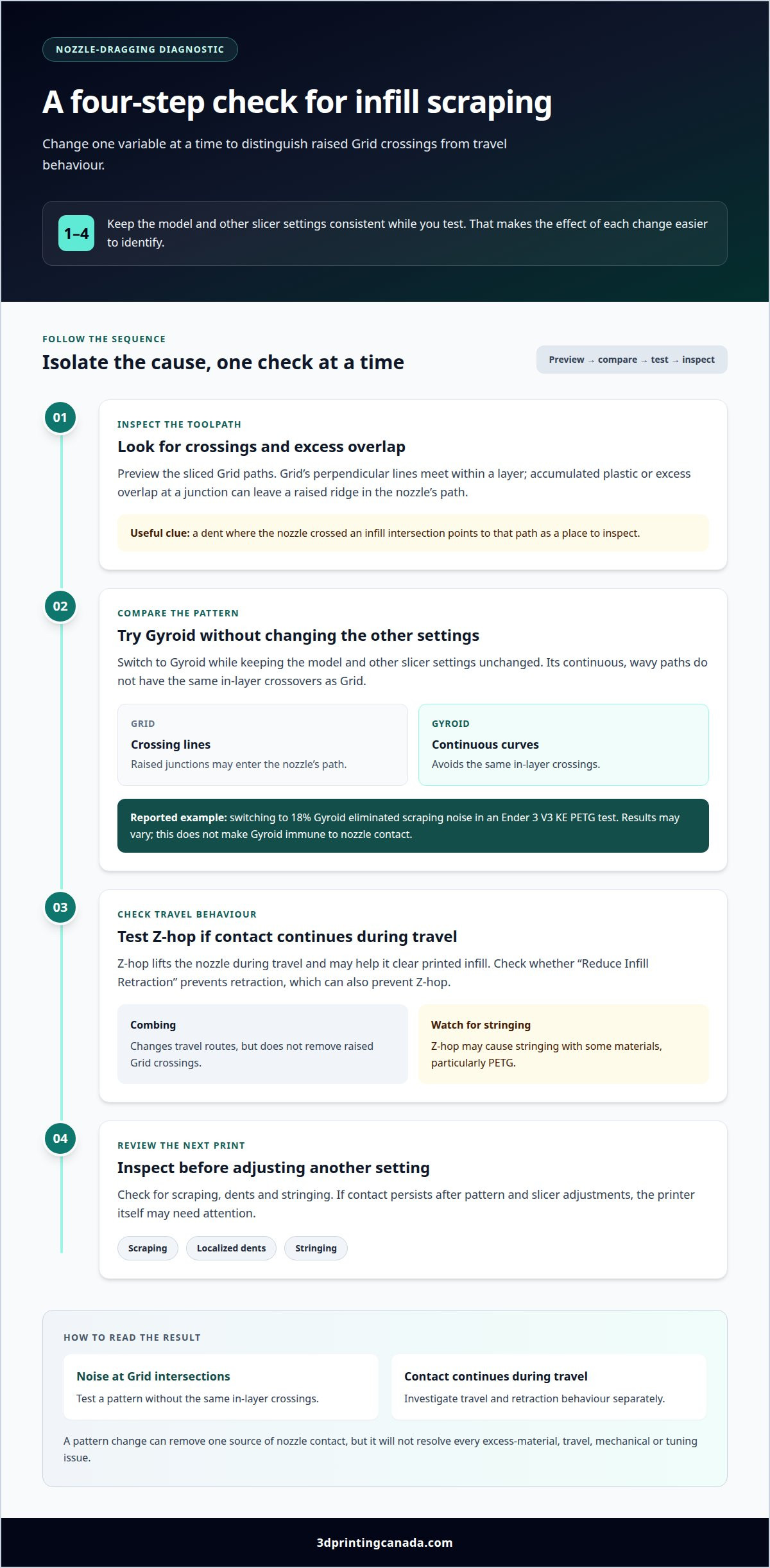
Use this sequence to isolate the cause without changing several settings at once:
- Preview the sliced Grid paths and look for line crossings or excess overlap.
- Switch to Gyroid while keeping the model and other settings unchanged.
- If contact continues during travel, test Z-hop and check whether infill retraction settings prevent it.
- Inspect the next print for scraping, dents and stringing before adjusting another setting.
If a pattern and slicer adjustments don’t resolve persistent contact, the printer itself may need attention. 3D Printer Repair Services can help address hardware issues affecting print quality.
A localized mark is more useful than a general impression of roughness. One printer user reported a small dent where infill lines crossed after the nozzle passed. Because Grid lines can cross within a layer and accumulate material at intersections, the dent’s location and timing suggest inspecting the infill path there. Not every scrape is caused by travel moves alone.
Gyroid is a useful alternative because its paths do not cross within a layer. If the dent disappears after switching patterns, that supports the possibility that Grid’s crossing geometry was involved. If it remains, check the other potential causes described above.
Grid infill structure and limitations
Grid builds each layer from two perpendicular sets of lines, creating a regular internal lattice. The part gains stiffness along those lines, but its response also depends on load direction and shell thickness. A bracket loaded parallel to its internal lines may behave differently from one twisted diagonally. Grid is a design choice, not a universal strength setting.
Consider how forces travel through the part. The outer shell carries load at the surface, while the infill supports it internally. A thicker shell can change how force spreads into Grid’s perpendicular paths. In a flat panel pressed from above, shell and infill work together; in a tab pulled sideways, the load may stress the grid across its line directions. Assess the whole part, not infill alone.
Grid’s regular geometry is easy to inspect in a slicer preview. Look for long, straight internal paths and consider whether the expected force follows or cuts across them. If the load changes direction, a pattern with more even directional behaviour, such as Gyroid, may be a better fit. Choose based on the forces the part must handle, not appearance alone.
More density isn’t automatically a better fix. Infill densities above 50% are rarely necessary and tend to increase thermal stress and internal shrinkage warping. Those effects can work against a clean, stable print, especially if the part’s shape already makes cooling uneven. Before raising density, review the shell thickness and the part’s load path. A stronger outer shell may address the need more efficiently than packing the core with extra lines.
Use this practical review before committing to a Grid design:
- Map the load: Identify whether the main force follows the grid lines, crosses them, or changes direction.
- Inspect the shell: Check whether the outer walls support the loaded areas, such as a bracket’s mounting points.
- Review density: Avoid treating values above 50% as an automatic strength upgrade; consider thermal stress and shrinkage warping.
- Compare patterns: Slice the same model with Grid and Gyroid, then compare their paths against the part’s expected forces.
Grid remains practical when its straight paths align with the part’s main loads and the shell supports the design. Its direction-dependent stiffness is a limitation when forces twist or change direction. Match the internal structure to the application, then validate the printed part under its intended conditions.
Why does a 3D printer nozzle drag on gyroid infill?
Gyroid removes Grid’s repeated crossings, but it cannot guarantee a clear nozzle path. During a curved infill pass, fresh filament can rise slightly above the intended layer height, and the nozzle may graze it along a nearby curve. If the scraping occurs throughout Gyroid rather than at a specific junction, inspect extrusion and travel behaviour before blaming the pattern.
Excess material is one possible cause. Over-extrusion can leave a thicker bead, while inconsistent flow can create local bumps along a smooth Gyroid path. Look for ridges or rough patches where the nozzle passes, then compare them with the slicer preview. If the preview is clean but the print shows excess plastic, investigate extrusion rather than infill geometry alone.
Retraction and Z-hop settings can affect clearance too. “Reduce Infill Retraction” can prevent retraction, which in turn can prevent Z-hop and leave the nozzle scratching the print. Check whether the option is active and whether travel moves lift the nozzle. This matters because curved infill still involves travel between separate printed regions.
Use a controlled test to narrow down the cause:
- Inspect the Gyroid preview and locate where the nozzle travels close to printed infill.
- Print a small section with the same filament, pattern and extrusion settings, then listen for contact.
- Check the affected surface for raised strands, flattened ridges or a scratch matching the nozzle’s travel path.
- Change one relevant setting, such as extrusion flow or infill retraction, then compare the next test.
Change one variable at a time so the result is easy to interpret. If adjusting retraction changes the scraping, travel clearance was involved. If raised, rough Gyroid lines remain, focus on extrusion consistency. Avoid changing the pattern, flow and travel settings together, or you won’t know which adjustment helped.
Also note when the sound starts. Contact on the first Gyroid layer suggests a different issue from scraping that appears after several layers. For later-onset rubbing, inspect the printed surface for accumulated material and compare the nozzle path with the new layer. A visible mark at one location gives you a specific spot to examine in the preview.
Gyroid may still suit the part when its continuous paths fit the design, but the printer must lay them cleanly. Use the sound, surface marks and slicer preview as clues. Together, they can help distinguish an extrusion problem from a travel-clearance issue, without treating every scrape as a reason to abandon Gyroid.
How do gyroid and grid infill compare for strength, print time, and material use?
Gyroid’s continuous, three-dimensional paths handle twisting and lateral forces more evenly. Grid provides stiffness along its two straight-line directions, but offers less even shear resistance. Infill density also affects compressive, tensile and flexural strength. When finding a gyroid infill vs grid infill nozzle dragging fix, weigh these strength differences alongside the toolpath and expected load.
Print time and filament use don’t necessarily move together. In a 100 mm cube benchmark at 15% density, Grid took 1 hour 42 minutes and used 112 grams of filament. Gyroid took 1 hour 48 minutes and used 108 grams. In that test, Gyroid took longer but used less material. The results apply to that cube and its settings, not every model or printer.
| Pattern | Strength behaviour | Benchmark time | Benchmark material |
|---|---|---|---|
| Grid | Stiff along its two line directions; less even shear resistance | 1 hour 42 minutes | 112 grams |
| Gyroid | More even across directions; suited to twisting and lateral loads | 1 hour 48 minutes | 108 grams |
Match the pattern to the part rather than relying on a single strength label. A bracket exposed to twisting may benefit from Gyroid’s more even response. A component loaded mainly along Grid’s straight paths may suit Grid, particularly when a shorter print estimate matters. Keep wall count, density and other slicer settings consistent when comparing estimates.
A useful gyroid infill vs grid infill nozzle dragging fix also considers the part’s force direction and the risk of nozzle contact. Compare the sliced paths, estimated time and filament use:
- Identify the force: Consider Gyroid for changing or twisting loads, and Grid when force follows its line directions.
- Compare consistently: Hold the model, density, walls and printer settings steady.
- Inspect the paths: Look for crossings or curves that could affect nozzle clearance.
For a functional part, test the printed geometry under its intended load. Infill density affects strength, and pattern alone can’t account for every shape or shell configuration. If printer motion or extrusion issues prevent consistent comparisons, explore 3D printer repair services as a practical next step.
Grid infill has a relative print speed of 100% baseline in the comparison table, so it serves as the reference point for that speed comparison. This is a relative measure, not a guarantee that every Grid job will finish at the same rate; model geometry, slicer settings and printer behaviour still affect an estimate. Its straight crosshatch provides strength along its two line directions, but it lacks Gyroid’s isotropic behaviour and shear resistance. Gyroid resists loads roughly evenly across directions and is particularly suited to twisting and lateral forces. These differences make the expected force direction as important as the speed comparison when selecting a pattern.
For functional prototypes that will be handled and stress-tested, the guide recommends gyroid infill at 25 to 40 percent density. For end-use parts under load, it recommends 40 to 60 percent gyroid infill paired with 3 or more perimeters. These recommendations give different starting points for prototypes and loaded parts, rather than a single density for every use. The right choice still depends on how the part will be used: a prototype facing twisting forces may benefit from Gyroid’s more even response, while a part loaded along Grid’s line directions may make use of its directional strength. Compare sliced estimates with the same model and settings, then test functional parts under their intended load.
3D Printing Canada: 3D Printer Repair Services
3D Printing Canada offers 3D Printer Repair Services for hardware issues that affect print quality. If nozzle contact continues after you’ve tested infill patterns and slicer settings, a printer fault may be contributing to the problem. A repair can address equipment issues that pattern changes alone won’t fix, helping you return to testing Gyroid or Grid with more consistent printer operation.
Before arranging a repair, note when the scraping starts and what you’ve already adjusted. Record whether it happens during infill travel or across printed paths, for example, and whether changing the pattern affected it. These details help describe the issue clearly.
Contact 3D Printing Canada to discuss a printer repair.
Build a more dependable print setup
Turn your next print into a useful baseline. Save the slicer profile that works well, note the filament and model, and record any changes. That gives you a reference if a future print behaves differently, rather than forcing you to start adjustments from scratch. A gyroid-versus-grid fix for nozzle dragging works best as part of a repeatable testing process, not a one-time guess.
Keep your baseline separate from experimental profiles. If a change improves clearance but affects the finish or print time, compare it with your saved settings before choosing what to use for the next part. This habit also makes it easier to describe a persistent printer issue and the steps you’ve tried.
For help with an equipment problem that continues beyond slicer adjustments, contact 3D Printing Canada. Keep testing, keep the settings that work, and make your next print with confidence.
Frequently Asked Questions
Why does a 3D printer nozzle drag on grid infill?
Grid infill can make the nozzle drag when deposited lines build up at crossings and form raised spots. Compare a scrape mark with the slicer preview to diagnose the cause. Repeated marks aligned with Grid junctions point to a path-related issue. If contact follows longer stretches instead, inspect extrusion consistency and travel clearance before changing infill density.
Does gyroid or grid infill reduce nozzle collisions and scraping?
Gyroid removes Grid’s in-layer crossings, reducing the risk of scraping on raised junctions. Grid’s straight paths may print faster, but intersections can create high spots. Neither pattern prevents all nozzle contact: excess material or travel settings can still cause rubbing over Gyroid paths. When switching patterns, keep other slicer settings unchanged for a useful comparison.
What are the risks of nozzle collisions, including layer shifts and print failure?
A nozzle collision can scar the print surface, dislodge deposited material or disturb the toolhead’s path. On a fast printer, repeated impacts may contribute to vibration or layer shifts, leaving the print misaligned. A severe shift can compromise the part or stop a print. If you hear a knock, inspect the affected layer and alignment before continuing a long job.