
Z-hop can help the nozzle clear small obstacles during travel, but it won’t fix the underlying cause. Common causes of nozzle scraping on printed infill include raised line crossings, excess material, curled infill, and plastic blobs stuck to the nozzle. Warping or a rough top surface can also put plastic in the nozzle’s path.
A scraping sound can be unsettling, and turning on Z-hop may seem like the quickest fix. It can reduce contact in some situations, but it may also hide an issue that needs attention. First identify when the scraping happens and what the nozzle is hitting.
This guide explains how infill patterns, extrusion flow, print surfaces, and warping can lead to nozzle contact, and which settings and physical issues to investigate. You’ll also learn when Z-hop is useful, when it only masks the cause, and how to spot signs that a collision may have shifted the print or affected the printer.
Key Takeaways
- Look for raised crossings, ridges, and plastic stuck to the nozzle when tracing the source of scraping.
- Consider whether excess material, soft curling infill, or weak support beneath the top skin is creating high spots.
- Choose an infill pattern with its path behaviour in mind; some patterns cross their own lines within a layer.
- Use the timing and location of nozzle contact to help distinguish infill bumps from a warped or lifted print.
- Treat Z-hop as a way to clear small travel obstacles, not as a fix for collisions or underlying printer issues.
Raised infill crossings and ridges
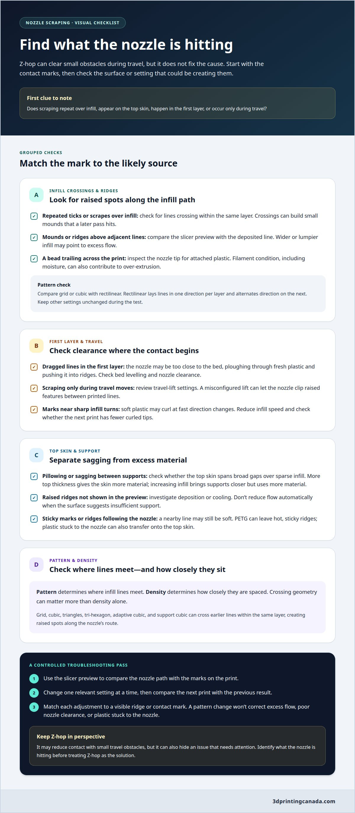
A nozzle can scrape when fresh infill sits higher than the toolpath expects. One clear example is a pattern that lays lines across one another within the same layer. Plastic can build into small mounds at each crossing, which the nozzle may hit on a later pass. This often sounds like a repeated tick or scrape over the infill.
Some infill patterns can create points where lines meet within a layer, which may give the nozzle raised spots to contact. Some infill patterns cross lines on the same layer, which can create raised spots. These intersections can form raised spots, especially if the printer deposits more material than the path needs. Crossing points and excess material are common causes of nozzle scraping on printed infill. Check whether contact repeats at intersections or occurs randomly across the surface.
Use the slicer preview to compare the nozzle’s path with marks on the print. Then make a small test print with rectilinear infill, which lays lines in one direction per layer and alternates direction on the next. If the noise changes with the pattern, crossings may be contributing. Keep other settings unchanged so the pattern is the main variable.
Raised lines can also indicate excess flow. Review the slicer’s flow ratio and run a flow calibration test if deposited infill looks wider or lumpier than it does in the preview. Filament moisture can contribute to over-extrusion, so consider the filament’s condition along with the flow setting. Another cause of nozzle scraping on printed infill is a plastic bead stuck to the nozzle, which can drag across the part and feel like a raised crossing.
- Check the pattern: Compare grid or cubic with a pattern that avoids same-layer crossings.
- Check the deposited line: Look for mounds at intersections or ridges above adjacent infill.
- Check the nozzle: Look for plastic attached to its tip and trailing across the print.
Ridges in the first layer need a separate check. If the nozzle starts too close to the bed, it can plough through fresh plastic, push it into ridges, and pick up a bead that trails behind the toolhead. Look for dragged lines in the first layer, then check bed levelling and nozzle clearance before changing infill settings. If scraping occurs only during travel moves, review the travel-lift settings too. A misconfigured lift can let the nozzle clip raised features between printed lines.
Fast infill can curl at sharp direction changes while the plastic is still soft. If marks appear near those turns, reduce infill speed and see whether the next print has fewer curled tips. Changing the pattern won’t correct excess flow, poor nozzle clearance, or plastic stuck to the nozzle. Match each adjustment to the ridge or contact mark you can see.
Rough top surfaces and inadequate infill support
A nozzle can scrape the top surface even if the infill pattern doesn’t cross itself. The top skin spans gaps between infill lines, much like a sheet resting on supports. If the gaps are wide or there are too few top layers, the skin can sag between supports. This uneven surface may rise above the nozzle’s planned path, creating ridges or a pillowed appearance.
Check the slicer preview where the top skin begins. If it bridges broad gaps over sparse infill, insufficient support may be the main issue. Adding top thickness gives the skin more material to form a flatter surface. Increasing infill can also bring supports closer together, but it uses more material and may not be the most efficient adjustment. Choose based on the model’s geometry and the support its top spans need.
Don’t reduce flow automatically just because the top looks rough. Excess material can create ridges, but a pillowed surface over sparse infill points to insufficient support. Compare the same area in the preview and on the finished print. If the planned surface is smooth but the print has raised ridges, investigate deposition or cooling. Sagging between visible infill supports suggests the top skin lacks enough backing.
Heat can also contribute. If a line is still soft when the nozzle passes nearby, it can deform instead of holding its intended shape. PETG can leave hot, sticky ridges on the top surface that follow the nozzle. Plastic stuck to the nozzle may also transfer onto the top skin, forming a bump that catches during a later pass. Look for material accumulating on the nozzle and raised marks that follow its route.
- Sagging between supports: Review top thickness and the infill beneath the affected area.
- Raised, repeated ridges: Compare the surface with the preview and inspect for excess material.
- Sticky marks: Check for plastic attached to the nozzle, especially when printing PETG.
Change one relevant setting at a time, then compare the next print’s top surface with the previous result. If added top thickness improves the surface, support was likely part of the problem. If ridges remain, examine flow, temperature behaviour, and nozzle cleanliness rather than adding infill without a clear reason. For persistent surface and contact issues, 3D printer troubleshooting support can help identify whether the cause is a setting or a hardware problem.
How do infill pattern and infill density affect nozzle collisions?
Pattern determines where infill lines meet, while density determines how closely they are spaced. Both affect the surface beneath the nozzle, but crossing geometry often matters more than density alone. Cubic, triangles, tri-hexagon, adaptive cubic, and support cubic can cross earlier lines within the same layer. These intersections may create raised spots along the nozzle’s route.
Grid also lays lines across one another on the same layer. Rectilinear takes a different approach: it prints in one direction per layer, then alternates direction on the next. Crosshatch can also alternate direction between layers. These paths avoid same-layer crossings, making them useful comparisons when scraping follows repeated infill intersections.
Density changes the spacing between infill lines. A denser structure may support the top skin more closely, but it also puts more material inside the part. If the pattern crosses itself, closer spacing doesn’t eliminate those crossings. It can increase the number of places where the nozzle passes near deposited material. Sparse infill, in contrast, can leave wider gaps beneath top layers, contributing to sagging rather than direct collisions.
Choose a pattern based on the part’s purpose, not just the sound. Gyroid avoids collisions with its own infill path and can suit parts that need resilience, though it may print slowly. Lightning infill can reduce material where internal support isn’t needed, but curling and extra travel moves can create other obstacles. Perimeters may add strength more effectively than simply changing the infill pattern.
- For simpler paths: Compare rectilinear with a crossing pattern such as grid.
- For resilience: Consider gyroid, while accounting for its slower print time.
- For reduced internal support: Consider lightning only where the model doesn’t need infill support.
A timed comparison using a Generic PLA profile and 15% infill showed different print durations across patterns: lightning took 3:22, while gyroid took 4:49. That comparison illustrates a trade-off, not a universal speed ranking; model shape and slicer settings affect results. Use the same model and settings when comparing patterns, then examine the infill preview for same-layer crossings and listen for contact in the corresponding areas.
If changing density alters the scraping, inspect the new line spacing and the surface beneath the nozzle. If a pattern change reduces it, crossings may be involved. If contact continues across different patterns, look elsewhere, such as flow, curled material, or travel behaviour. Change one slicer setting at a time so each test points to a clear cause.
How to tell whether nozzle scraping is caused by infill or warping?
Start by locating the contact marks. Scraping that repeats over internal lines or intersections points to infill height or path geometry. Contact across a broad section of a large, flat print suggests the part may have warped upward. A lifted corner can also enter the nozzle’s path, even while the printer follows its planned layer height.
Compare the print’s shape with the slicer preview. If the preview shows the nozzle passing close to raised infill and the sound follows those same internal routes, infill is a likely contributor. If the preview looks clear but the finished part has a bowed centre or curled edge, inspect the surface itself. Cooling-related warping can lift the middle of a large, flat print, causing the nozzle to rattle as it passes over the infill below.
Note where contact begins and how it changes. A scrape that starts at a corner and continues after it lifts differs from a repeated bump at separate infill crossings. A warped centre may cause contact over a wider area, while a raised edge usually leaves marks near the perimeter. Observe whether the noise follows the toolpath or stays tied to one raised part of the model.
- Repeated internal marks: Compare their positions with infill lines and crossings in the preview.
- Raised centre: Check whether a broad, flat area has bowed upward.
- Lifted corner or edge: Look for a gap between the print and build surface.
- Contact during travel: Check for curled edges, loose features, or raised intersections along the nozzle’s route.
Z-hop may reduce contact by lifting the nozzle during travel, and lowering travel speed may soften the impact. Neither adjustment flattens a curled edge or corrects a warped centre. If contact stops with Z-hop, the nozzle may simply be clearing an obstacle, so the part’s shape still matters. A rising corner can continue to distort later toolpaths even if the nozzle no longer scrapes it.
Use a controlled comparison to narrow down the cause. Keep the model and other slicer settings unchanged, then alter one factor that matches the evidence. If the preview shows repeated crossings, test a non-crossing pattern. If the print has a lifted edge, address the part’s adhesion and cooling conditions instead. Changing the infill pattern and travel behaviour at the same time makes it harder to tell which adjustment affected the sound.
Finally, inspect the print while it’s still on the build plate. A visible gap beneath a corner or a raised centre confirms the nozzle is meeting a physical high spot, not just reacting to infill geometry. Note the contact location and compare it with the next print’s surface before making another change.
Can nozzle scraping damage a print, hotend, or stepper motor?
Light contact over infill may leave only surface marks, and ordinary nozzle wear from small infill bumps is negligible. A hard collision is different. It can bend the nozzle, shift the part or build plate, or disrupt the printer’s position. The risk depends on the force of the contact and whether the nozzle keeps hitting the same obstacle.
Check the print first for gouges, dragged lines, shifted layers, or a sudden change in alignment. If the part or build plate moves, the remaining toolpath no longer matches the object’s physical position. The printer may continue in the wrong place, producing a visibly misaligned result even after the original collision has passed.
A forceful impact can also affect motion components. A stepper motor may lose position, or a pulley may slip, so later movements no longer land where the slicer planned. Watch for shifted layers after a collision, unusual movement, or a toolhead that no longer follows its expected path. Stop the print if repeated impacts or a sudden alignment change occur.
Inspect the nozzle and hotend before starting another print. A bent nozzle can alter the extrusion path or keep contacting the model. After maintenance, a loose or incorrectly seated hotend, nozzle, bed, or gantry can also cause contact across the print. Check that hotend screws are tightened into the heatsink and that the nozzle is fully tightened. Follow the printer manufacturer’s procedure for any adjustment.
- Surface scuffing: Check whether marks stay local to the infill contact area.
- Layer shift: Compare the print’s edges and features above and below the collision.
- Changed nozzle position: Inspect the hotend assembly and mounting after impact or maintenance.
- Part or plate movement: Stop printing and assess alignment before resuming.
Don’t rely on Z-hop to protect against a hard collision. It may clear a small obstacle during travel, but it won’t correct a bent nozzle, slipping pulley, or shifted build plate. Find and address the source of contact before another long print risks repeating the impact.
If a collision has left the nozzle, hotend, or motion system out of alignment, book 3D printer repair service to have the hardware issue assessed and repaired.
3D Printing Canada
3D Printing Canada offers 3D Printer Repair Services for printer issues that persist after you’ve checked slicer settings and print surfaces. If scraping continues across different infill patterns, or a collision has shifted the print or affected the hotend, a repair assessment can help address the hardware problem. Share when the scraping occurs and any changes you’ve already tried, such as adjusting travel behaviour or infill. That context helps narrow down whether the issue points to the hotend, bed, gantry, or another printer component. For scraping that appears tied only to a particular pattern or raised surface, continue with settings-based troubleshooting first. If your printer needs mechanical attention, contact 3D Printing Canada to discuss its repair service.
Make your next print a clearer test
Make the next print a useful comparison, not another guess. Record the slicer profile, filament, infill pattern, and location of contact. A short note can show whether a change affects the same area or shifts the problem elsewhere. Over time, this makes nozzle scraping on printed infill easier to distinguish from a separate mechanical issue.
If the printer still scrapes after settings and print-surface factors have been considered, a hardware assessment may be the practical next step. 3D Printing Canada offers 3D Printer Repair Services for printer issues that need technical attention. Share the symptoms and what you’ve already observed so the repair discussion can start with useful context.
Contact 3D Printing Canada to discuss a printer issue. Keep testing methodically, and you’ll be better equipped to get back to reliable prints.
Frequently Asked Questions
Should you turn on Z-hop?
Turn on Z-hop if the nozzle clips small obstacles during travel, but treat it as a clearance adjustment, not a repair. Test it on a short print and listen for contact during non-extruding moves. If scraping continues while the nozzle lays down infill, Z-hop won’t address the cause. Note whether the setting changes stringing or travel behaviour, and keep it only if the print benefits.
Why does a 3D printer nozzle scrape across printed infill?
A nozzle scrapes when printed plastic rises into its path. This height difference can result from crossing lines, uneven extrusion, a curled feature, or a lifted print surface. Timing offers a useful clue: contact during extrusion points to the printed path, while contact between lines points to travel clearance. Compare the sound and visible marks with the toolhead’s movement to narrow down the source.
Can over-extrusion cause nozzle scraping on infill?
Yes. Excess flow deposits more plastic than the infill path requires, so lines can become wider or form raised areas. Check the slicer’s flow ratio and run a flow calibration test rather than changing several extrusion settings at once. Filament moisture can also contribute to over-extrusion. If the same filament prints differently after storage, consider its condition along with the profile before adjusting flow.
Can Z offset, bed levelling, or Z-axis problems make the nozzle scrape prints?
Yes. An incorrect Z offset can place the nozzle too close to the bed, while uneven bed levelling can create different clearances across the build surface. A Z-axis movement problem may also affect nozzle height as layers progress. If contact starts on the first layer or varies across the bed, revisit levelling and Z offset. If it appears after maintenance, inspect for loose or incorrectly seated printer components.
What settings prevent nozzle collisions with infill on FDM printers?
No single setting prevents every collision. For a useful test, keep the model and flow settings unchanged, then compare a crossing pattern with rectilinear infill. If top layers sag, improve their support with the slicer’s top-layer or infill settings instead of relying on travel clearance alone. Review infill speed if sharp turns deform the lines. Make one adjustment per test so you can identify which setting helped.
Should avoid-crossing-perimeters or Z-hop be enabled to stop nozzle scraping?
These settings address different movements. Avoid-crossing-perimeters can route travel moves away from printed outer walls, but it doesn’t remove raised infill inside the model. Z-hop lifts the nozzle during travel and can help clear small obstacles. Try the setting that matches where contact occurs, then compare the travel path in the slicer preview. If scraping happens while printing infill, address the infill or extrusion cause instead.