
A crisp, detailed print can still be the wrong size. A hole may come out too tight, a mating part may not fit, or the same CAD model may produce different results between builds. That’s why rapid prototype dimensional accuracy optimization takes more than tweaking a slicer setting and hoping for the best.
If printed features don’t match the model, the cause could be the design, printer setup, material, or measurement method. Changing several variables at once makes the cause harder to identify. A repeatable test-and-measure workflow gives you a clearer path from mismatch to improvement.
This guide explains how to measure critical dimensions, investigate possible sources of error, and make targeted design or print adjustments. You’ll also learn how to validate changes, account for material behaviour and printer calibration, and decide whether a result is accurate enough for its intended purpose. The goal is a practical feedback loop: measure, adjust, print, and check again.
Key Takeaways
- Separate dimensional accuracy from precision, repeatability, surface finish, and resolution to identify what your prototype needs to improve.
- Record the CAD dimension, measured result, and deviation, then compare the same feature across repeat prints before changing settings.
- Use rapid prototype dimensional accuracy optimization to guide focused tests of design compensation, printer calibration, slicer settings, and material control.
- Track each model revision, printer, material, profile, orientation, and measurement so you can trace which changes make a difference.
- Choose measurement tools for the feature and inspection task. Scanning can help with complex shapes, while contact tools may suit accessible dimensions.
What Dimensional Accuracy Means in Rapid Prototyping
Dimensional accuracy describes how closely a measured feature on a printed part matches the corresponding dimension in its CAD model. If a model specifies a hole diameter, for example, accuracy describes how close the printed hole’s measured diameter is to that intended value. The difference is the deviation. There’s no single tolerance for every prototype: an acceptable deviation depends on what the part needs to demonstrate and how it will be used.
Keep accuracy separate from related concepts. Precision describes how closely measurements or results cluster together. Repeatability is the ability to get similar results again under the same conditions. Surface finish describes the texture of the part, while printer resolution refers to the smallest detail the system can reproduce. A fine-looking print with small features isn’t automatically dimensionally accurate.
Accuracy, precision, and repeatability are different
Imagine printing the same shaft several times. Each one measures slightly larger than its CAD dimension, but the measurements are close to one another. The results are repeatable and precise, but consistently oversized, so they’re inaccurate. That pattern points to a systematic deviation to investigate. It doesn’t show that the part meets its intended dimensions.
Measurement resolution is different again: it describes the smallest increment a tool can display, not how close its reading is to the true dimension. A detailed readout can’t correct poor measuring technique or an unsuitable tool. One successful print is also only one result. To assess repeatability, compare prints made under the conditions you want to rely on.
Set a fit-for-purpose tolerance before printing
First decide what the prototype must prove. Is it for checking appearance, confirming overall size, testing an assembly, or evaluating how parts fit together? The answer determines which dimensions deserve close attention. Mark critical features such as holes, slots, mating faces, and the part’s overall envelope, then agree on acceptable deviations with the project team.
A prototype used to assess general shape may not need the same dimensional control as one intended to verify an assembly. A hole that looks right may still be too small for a fastener, while a slightly rough outer surface may not affect a fit test. Set tolerances for the application and prototype stage instead of applying one assumed value to every feature. This gives rapid prototype dimensional accuracy optimization a clear target and helps you judge results by function, not appearance alone.
How to Diagnose Dimensional Error Before Changing Print Settings
Start with evidence, not a settings sweep. Choose a dimension that matters to the prototype, then record its CAD value, measured value, and deviation, including whether the printed feature is larger or smaller than intended. Use the same measurement method and contact points each time. This baseline helps you spot a consistent offset, variation between builds, or a result that may be caused by measurement technique.
Diagnostic rule: Verify the measurement and printer setup before changing multiple slicer settings. Print the same test again under the same conditions before deciding an adjustment worked. If you change flow, temperature, speed, and orientation together, you won’t know which change affected the result. For effective rapid prototype dimensional accuracy optimization, keep each test focused and document what changed.
Check the model, orientation, and measurement method
Before investigating the machine, confirm that the CAD model and exported file agree. Check units and scale, inspect the mesh for errors, and make sure you’re measuring the intended feature rather than a nearby edge or surface. Record the model revision so a file change doesn’t get mistaken for a printer effect.
Orientation can influence how features form and where support material touches the part. A hole or slot printed in a different direction may measure differently, and support contact can affect the surface being checked. Keep orientation consistent during comparisons. Use a suitable measuring tool, place it at the same points, and avoid squeezing flexible parts, which can distort the reading.
Separate printer, material, and process causes
Look for patterns before selecting a cause. A similar offset across different features may suggest a broader scaling or calibration issue; variation between otherwise identical prints may point to inconsistent setup or machine behaviour. Check relevant mechanical and calibration conditions, including frame rigidity, belt tension, extruder calibration, and extrusion consistency. Don’t assume a slicer setting is responsible before checking the basic setup.
Material can also affect the result. Confirm the filament type and handling, and follow the manufacturer’s guidance before attributing a dimensional change to shrinkage. Keep the material and relevant environmental conditions consistent during a comparison. Then use a simple test part that isolates the feature or issue you’re investigating, changing only one relevant factor between tests.
- Same deviation on repeated prints: Check for a consistent model, calibration, or process offset.
- Different results between prints: Review setup consistency, material handling, and printer condition.
- Only one feature is affected: Recheck its geometry, orientation, supports, and measurement approach.
If the same errors persist after controlled checks and appear tied to printer hardware, professional 3D printer repair services may be worth considering. Keep your measurements and test conditions on hand to help explain the pattern.
Compare the Main Ways to Improve Rapid Prototype Accuracy
There’s no single adjustment that fixes every dimensional error. A consistent offset across features may call for a different response than a hole that prints poorly or dimensions that vary between builds. Match the intervention to the pattern, then consider what the prototype needs to prove. A fit-check model and a prototype for evaluating overall form may have different priorities.
Use this comparison to choose a controlled test. Follow your printer and material documentation for recommended settings, calibration steps, and handling. Avoid universal parameter prescriptions: a change that helps one setup may create new problems in another.
| Symptom | Likely cause | Test | Adjustment | Trade-off |
|---|---|---|---|---|
| Several dimensions show a consistent offset | Model scale, calibration, or a repeatable process effect | Check the model and compare the same features across controlled prints | Correct the source, or apply documented CAD compensation if the offset persists | Compensation can mask an underlying setup issue or affect other features |
| Holes or slots don’t fit as intended | Feature geometry, orientation, or process limits | Print a small test with the relevant feature and intended orientation | Revise geometry or fit allowance, then validate the mating part | More clearance may improve assembly but reduce a snug fit |
| Dimensions vary between builds | Calibration, mechanical condition, material handling, or changing process conditions | Repeat a test while holding the setup and material consistent | Check equipment and material controls before tuning the slicer | Extra checks take time but help avoid tuning around an unstable cause |
| Surface or edges look inconsistent | Extrusion, motion, temperature, or build conditions | Inspect the affected area and change one relevant setting at a time | Adjust the setting indicated by the test, following documentation | Settings can interact, so improving one feature may affect another |
When design compensation is appropriate
Consider CAD compensation only after confirming that the deviation is consistent and repeatable. Fit and assembly allowances are design decisions based on intended use, not automatic corrections for every undersized hole or oversized edge. Record the compensation in the model notes or revision history so a later redesign doesn’t apply the same correction twice.
When process tuning or equipment checks make more sense
Look for clues in the print: uneven extrusion, shifted features, or changes around supported surfaces point to different checks. Review motion, extrusion, temperature, and build conditions as relevant. Because settings can interact, change one factor and compare results rather than making broad adjustments. If the same issue persists and suggests a hardware problem, consider a repair assessment.
Use rapid prototype dimensional accuracy optimization as a decision process: measure the pattern, test its likely cause, and select the least disruptive adjustment that meets the prototype’s purpose. Recheck affected features after each change, since a local improvement can alter fit elsewhere.
A Repeatable Workflow for Optimizing Dimensional Accuracy
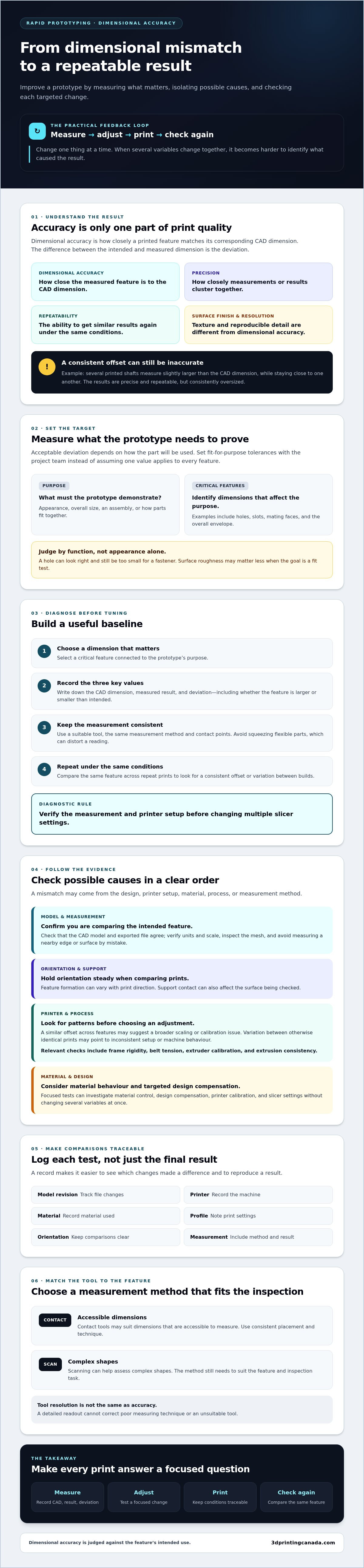
Turn each print into a controlled learning cycle: define the critical dimensions, print a test, measure the result, diagnose the pattern, adjust one relevant factor, then validate the revised part. This keeps rapid prototype dimensional accuracy optimization tied to project requirements rather than trial and error.
- Define: Select features that relate to the prototype’s purpose, such as a hole that must accept a fastener or a face that mates with another component.
- Print: Use a representative test part and record its orientation and production conditions.
- Measure: Use a consistent method and note readings for the same features each time.
- Diagnose and adjust: Identify the likely source, change one factor, and record exactly what changed.
- Validate: Reprint and check whether the relevant dimensions, fit, or function now meet the project’s agreed criteria.
Match the tool to the feature. Calipers can check accessible outside dimensions and some internal features; gauges can quickly assess whether a hole or slot accepts a specified mating feature. For complex curves or a broader shape comparison, a 3D scanner can capture surface geometry for inspection. Scanning and contact measurements serve different needs, so choose based on access, geometry, and the confidence your decision requires. For a closer look at options, read the 3D scanner selection guide.
Build a useful test and measurement record
Don’t track only the part’s overall length and width. Include representative critical features, such as a hole, slot, mating face, or wall, and measure each using the same tool and method. Repeat readings consistently and record the observed variation. This helps distinguish a stable offset from results that shift between measurements or print iterations.
A simple log can capture the model revision, printer, material, slicer profile, orientation, CAD dimension, measured values, deviation, and adjustment made. Add notes about relevant conditions, such as material handling or setup changes. Keep entries together so you can compare iterations instead of relying on memory.
Validate the revised prototype against its purpose
After a controlled adjustment, reprint the geometry that tests the affected feature. Check the measurements, then assess fit or function against the criteria agreed with your project team. If repeatability matters, compare results across additional builds under the conditions you expect to use.
Keep earlier profiles and model revisions available. A clear record makes successful changes traceable and gives you a reliable starting point if a later design or material change affects the result. If you’re selecting scanning equipment for dimensional inspection, explore 3D scanners as part of your measurement workflow.
Choose Tools and Support That Keep Accuracy Improvements Practical
The right measurement method depends on what you need to check: a small opening, an accessible outside dimension, or a complex surface. Match the tool to the feature, how easily you can reach it, and how confident you need to be in the result. No tool makes every measurement reliable by itself; technique and consistent use matter too.
Select measurement tools for the part
Calipers are useful for accessible dimensions, such as a part’s width or the outside diameter of a shaft. Keep the jaws square to the feature and use consistent pressure. Readings can be misleading if the jaws sit at an angle, the surface is uneven, or a flexible part is compressed. Check that the instrument suits the dimension you’re measuring.
For a specific fit or opening, a suitable gauge can make repeated checks straightforward. It can tell you whether a mating feature passes or fits as intended, but it won’t provide a complete dimensional record. A 3D scanner can help inspect complex shapes and compare broad surface geometry with a digital model. Treat scan results as one inspection method, and verify critical dimensions with a suitable contact tool or gauge when a decision depends on a specific measurement.
Know when to get equipment or technical help
Let the diagnostic pattern guide your next step. If you need to inspect curved geometry, consider whether scanning fits your workflow. If material behaviour is changing between tests, review filament handling and manufacturer guidance. If your current printer can’t produce a stable result under controlled conditions, compare printer options against the materials and features your prototypes require. Each tool supports the process; none guarantees a particular accuracy outcome.
If recurring deviations remain after controlled calibration checks, the cause may involve the printer’s mechanical condition. Professional repair support may be appropriate when you suspect a hardware issue. Bring along your test measurements and setup notes so the problem can be discussed with useful context.
For practical rapid prototype dimensional accuracy optimization, choose equipment or support to address the issue you’ve identified, rather than buying tools or changing hardware by guesswork. 3D Printing Canada offers 3D printers, 3D scanners, filaments, and professional 3D printer repair services. Review the options that fit your workflow in 3D printing equipment and support.
Make Your Next Prototype a Measured Improvement
Better dimensions come from a repeatable feedback loop, not a collection of untested setting changes. Define which features matter, measure them consistently, and record each adjustment so you can connect results to causes. Then validate the revised part against its intended fit or function.
That’s the practical value of rapid prototype dimensional accuracy optimization: each test helps you make a more informed decision, whether the right next step is refining the design, checking printer setup, reviewing material handling, or improving your measurement approach. Aim for accuracy that suits the prototype’s purpose instead of chasing an arbitrary target.
If you’re considering equipment or technical support for your workflow, 3D Printing Canada sells 3D printers, 3D scanners, and a range of filaments, and provides professional 3D printer repair services. Explore 3D printing equipment and support to see what may suit your needs. Keep testing one change at a time, and let the measurements guide your next build.
Frequently Asked Questions
What is dimensional accuracy in rapid prototyping?
Dimensional accuracy describes how closely a measured feature on a printed prototype matches the corresponding dimension in its CAD model. If a model calls for a slot of a particular width, compare that intended width with a consistent measurement of the printed slot. Accuracy differs from repeatability: several prints can match one another closely yet all differ from the CAD dimensions.
How can I improve dimensional accuracy in a 3D printed prototype?
Improve accuracy by measuring important features, checking the model and printer setup, then testing one relevant adjustment at a time. Confirm units and scale, keep orientation and material consistent, and record the CAD dimension alongside each measurement. Repeat the print to see whether the change holds. This measured approach makes rapid prototype dimensional accuracy optimization more reliable than changing several settings at once.
Why is my 3D printed part larger or smaller than the CAD model?
A part can differ from its CAD dimensions because of model scaling, printer calibration, extrusion or motion behaviour, slicer settings, material properties, or measurement technique. The pattern offers clues: a consistent offset across features differs from variation between builds or an issue limited to one hole. Check the model and measuring method first, then investigate printer, material, and process factors with a controlled test.
Does a smaller layer height improve dimensional accuracy?
Not necessarily. A smaller layer height can change how a surface or sloped feature is formed, but it doesn’t automatically make a part’s dimensions closer to the CAD model. Dimensional results also depend on factors such as calibration, material, orientation, and other print settings. Test layer height only when it’s relevant to the feature, and compare measurements while keeping other conditions stable.
How do I measure a 3D printed prototype accurately?
Choose a tool suited to the feature, then use the same method and contact points for each comparison. Calipers can check accessible dimensions; gauges can assess specific openings or fits. Keep the tool square to the feature, use consistent pressure, and avoid compressing flexible parts. Record the CAD value and measured result, and repeat the measurement to spot inconsistent readings.
Can I correct dimensional error by changing the CAD model?
Yes, CAD compensation can account for a consistent, repeatable deviation or provide a deliberate allowance for a fit or assembly. First confirm that the model, measurement method, and printer setup are sound. Then document the change in the model revision so it isn’t applied twice later. Validate the revised geometry with a new print and check the relevant dimensions and fit.
When should I use a 3D scanner to check prototype accuracy?
Consider a 3D scanner when you need to inspect complex curves, freeform surfaces, or overall shape that’s difficult to capture with contact tools. A scan can help compare surface geometry with a digital model, but it may not replace direct measurement for a critical hole or fit. Verify important dimensions with an appropriate contact tool or gauge, and select a scanner suited to your inspection task.