
A clean-looking resonance graph can still point you toward the wrong input-shaper settings. If an accelerometer is mounted loosely, wired incorrectly, or configured for a different sensor, its measurements may mislead rather than help. This input shaping accelerometer calibration guide starts with the part that’s easiest to overlook: reliable results depend on a sound setup, not just a calibration command.
It’s understandable to be unsure which connection and configuration suit your printer, or how to turn resonance peaks into settings without introducing new print defects. Follow a repeatable Klipper workflow to identify your accelerometer setup, check the printer’s mechanical condition, measure X- and Y-axis resonances, and choose shaper settings based on the results.
You’ll also learn what to look for in the graphs, how to spot measurements that may not be trustworthy, and what to check before running a test again. Then verify the changes with a print and assess the finish before moving on to pressure advance. Take it one step at a time, and you can make calibration decisions based on evidence instead of guesswork.
Key Takeaways
- Identify your accelerometer model and connection method before following sensor-specific wiring and Klipper configuration steps.
- Use the input shaping accelerometer calibration guide to compare measured resonance data with candidate shapers, smoothing, and acceleration limits.
- Keep test conditions consistent so you can distinguish unusual measurement results from changes in the printer or setup.
- Check belts, frame rigidity, and moving parts before relying on software compensation to address ringing or ghosting.
- Assess the practical result with a test print, then investigate persistent hardware issues if calibration doesn’t improve print quality.
What input shaping accelerometer calibration measures in Klipper
Klipper input shaping uses measured printer vibrations to choose motion-compensation settings that can reduce ringing or ghosting. During resonance tests, an accelerometer records how the printer moves. Klipper analyses the data and recommends a shaper type and frequency. The sensor measures motion, not print quality. The resulting settings are a software response to the printer’s measured behaviour.
Ringing appears as repeated outlines beside sharp edges, while ghosting can look like a faint echo of a feature across the print surface. These artefacts may appear when a moving part continues to vibrate after a quick change in direction. Input shaping adjusts motion commands to reduce the effect of those vibrations on a print. It can help, but it won’t guarantee a flawless result or repair a mechanical fault.
What does an accelerometer measure on a 3D printer?
During a Klipper resonance test, the printer moves along an axis in a controlled pattern while the accelerometer records changes in acceleration. The readings show how the tested assembly responds to motion. Think of a ruler held at one end: tap it, and it wobbles most strongly at a particular rate. That natural rate is its resonance frequency. A printer’s frame, toolhead, belts, and other moving parts also have vibration patterns.
The sensor data helps Klipper identify those patterns and assess possible input-shaper settings. A resonance frequency is not itself a shaper setting, and the accelerometer doesn’t install or apply compensation. The shaper type and frequency are configuration choices informed by the measurement. The recommendations depend on the recorded data and the printer’s motion characteristics.
When is accelerometer calibration useful?
Accelerometer calibration is useful when a Klipper-controlled printer shows ringing, particularly after sharp corners or other quick direction changes. Faster motion and higher acceleration can make vibration-related marks more noticeable because the machine changes speed and direction more aggressively. A measurement-based test can help replace trial and error with data about the printer’s response.
Measurements describe the setup as tested, not the printer indefinitely. Changes such as a different toolhead, altered belt tension, or added mass can affect how the machine vibrates. After changing the printer’s hardware, consider whether the old results still represent its current configuration.
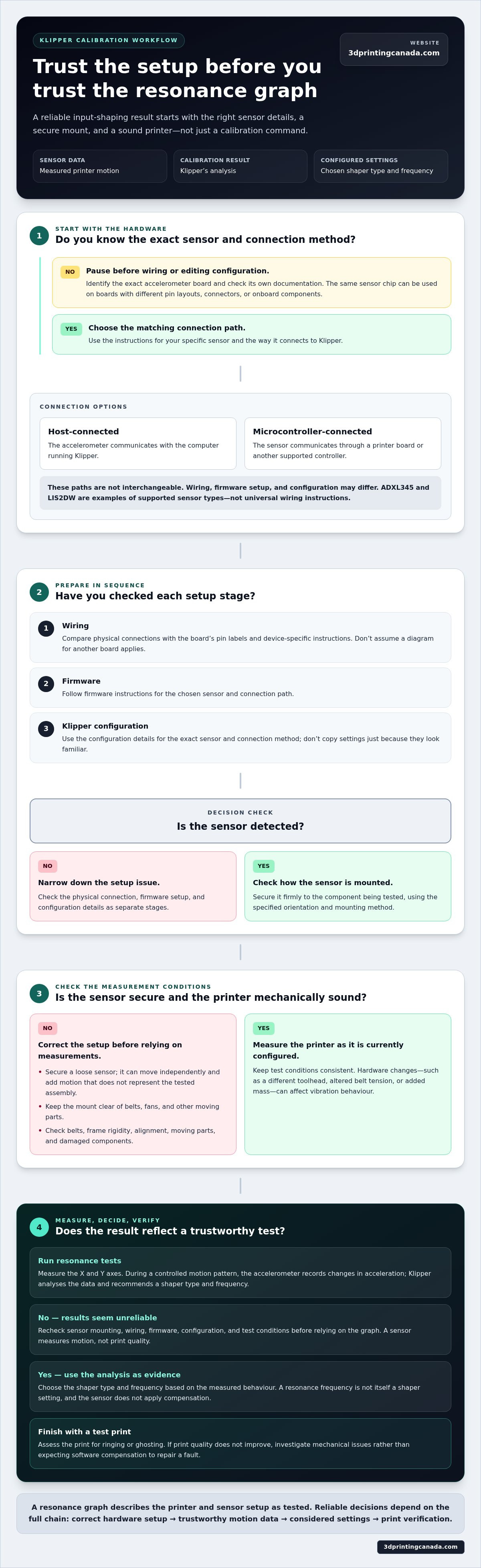
Use calibration alongside basic mechanical checks and suitable print settings. A loose belt, flexible frame, misaligned motion system, or damaged part can cause problems that software compensation won’t correct. Before interpreting the results, keep these three steps distinct:
- Sensor data: the printer’s measured motion during the test.
- Calibration result: Klipper’s analysis of that data.
- Configured settings: the chosen shaper type and frequency used to compensate for resonance.
This input shaping accelerometer calibration guide treats those as separate steps. Knowing the difference makes it easier to understand what a graph can tell you, and what still needs attention in the printer or print settings.
Prepare the accelerometer, printer, and Klipper configuration
Before changing configuration or connecting wires, identify the exact accelerometer model and how it will communicate with Klipper. A sensor name alone isn’t enough: boards using the same chip can have different pin layouts, connectors, or onboard components. Start with the documentation for your specific board, then follow the instructions for its connection method. This helps prevent a common setup mistake: copying a familiar-looking configuration that doesn’t match the hardware.
Handle preparation in three stages: wiring, firmware, and Klipper configuration. Check each stage before moving on. If the sensor isn’t detected, this approach helps narrow the cause to a physical connection, firmware setup, or configuration detail instead of leaving you to troubleshoot everything at once.
Choose the correct accelerometer connection path
A host-connected accelerometer communicates with the computer running Klipper. A microcontroller-connected sensor communicates through a printer board or another supported controller. These paths aren’t interchangeable, and may require different wiring, firmware setup, and configuration. ADXL345 and LIS2DW are examples of supported sensor types, not universal wiring instructions. Check current Klipper guidance for your exact sensor and connection method before assigning pins or editing configuration.
Pay close attention to the pin names and firmware options for your connection path. Don’t assume a diagram for one board applies to another, even if both use the same accelerometer chip. Note the sensor model, the controller it connects to, and the relevant documentation. Then compare each physical connection with the board’s pin labels and device-specific instructions.
Mount and check the sensor before measuring
Secure the accelerometer firmly to the component Klipper will test, using the orientation and mounting method specified for that sensor. A loose board can move independently of the printer and add motion that doesn’t represent the tested assembly. Keep the mount rigid and clear of belts, fans, and other moving parts. If the instructions specify an axis orientation, follow it rather than relying on the direction the connector faces.
Before running a resonance test, check the setup in this order:
- Wiring: Compare connector orientation and pin connections with the sensor and controller documentation. Make sure the wires are secure and won’t snag during movement.
- Firmware: Verify that the firmware was built and flashed for the chosen sensor connection path, following current Klipper instructions.
- Configuration: Check that the sensor section and pin names match the exact hardware. Don’t paste a sample configuration without confirming each value.
- Communication: Use Klipper’s available status or diagnostic feedback to confirm that the sensor is recognized before collecting data.
- Test area: Remove loose tools and objects from the printer and its motion path. Check that the toolhead and bed can move without obstruction.
This input shaping accelerometer calibration guide treats a successful sensor check as a separate milestone from calibration. If the device isn’t recognized, resolve that first; test data from an uncertain setup won’t be useful. If the connections and configuration look sound but a mechanical issue persists, professional 3D printer repair services can help address hardware problems that calibration can’t correct.
Compare calibration approaches and interpret resonance results
Manual tuning and accelerometer-based calibration both help you choose input-shaper settings, but they use different evidence. Manual tuning compares the visible results of print tests. Accelerometer-based calibration records motion during a controlled test, which Klipper analyses to suggest shapers and related limits. The sensor-based approach is more data-led, but suggested settings still need to be assessed on a real print.
Read the results as a set of trade-offs, not a single score. A setting that reduces vibration effects may also increase smoothing, which can soften details or corners. Klipper’s acceleration guidance helps explain the performance trade-off, but it doesn’t guarantee that every print can run at that limit. This input shaping accelerometer calibration guide separates what the printer measured from the settings you’ll verify in practice.
What do the resonance graphs and shaper suggestions mean?
A graph peak indicates that the tested printer responds more strongly to motion at that frequency. It helps identify resonance, but doesn’t tell you by itself which shaper to use. Candidate shapers, such as MZV or EI, are different ways to compensate for the measured response. Compare their smoothing and acceleration implications as well as their effect on vibration.
Klipper’s output brings several kinds of information together. Use this guide to distinguish them:
| Result | What it tells you | How to use it |
|---|---|---|
| Measured resonance | Frequencies where the tested axis responds to vibration. | Use the graph and reported values to understand the machine’s motion response. |
| Candidate shaper | A suggested algorithm and frequency for compensation. | Compare alternatives using Klipper’s output and documentation. |
| Smoothing | The degree of smoothing associated with a shaper choice. | Consider whether the trade-off suits the detail and surface finish you want. |
| Acceleration limit | Guidance on acceleration in relation to the selected shaper. | Treat it as a recommendation to evaluate, not an automatic target. |
How should you choose between suggested settings?
Start with Klipper’s recommendations and the current documentation for your specific output. If Klipper presents two candidates, compare their reported smoothing and acceleration guidance rather than choosing by name alone. Apply a suitable configuration, then evaluate a physical print for ringing, corner definition, and other visible changes.
A Klipper suggestion reflects measured data, but it can’t guarantee the same print results on every printer. Mounting, mechanics, materials, and print settings all influence the finished part. Treat a configuration entry as a starting point, not proof that an artefact has been resolved. Keep test conditions consistent when comparing results, and avoid changing several print variables at once. That makes it easier to connect a visible improvement or drawback to the setting you changed.
Use the resonance graph to understand the measurement, the shaper suggestion to guide configuration, and a print to judge the outcome. If a peak looks unusual or the recommendations don’t make sense, review current Klipper guidance before settling on a setting.
Calibrate input shaping with an accelerometer step by step
Work through calibration in stages: confirm the sensor responds, measure the printer’s axes, review Klipper’s recommendations, then save and test the settings. In short, verify the accelerometer, measure resonance, run shaper calibration, save the recommended configuration, and check the result with a consistent print. The commands below are standard Klipper console commands. Follow current Klipper and sensor documentation if your setup requires a device-specific variation.
Run the measurement and calibration sequence
Start only after the sensor is mounted and configured. Clear obstructions from around the printer, and make sure the toolhead and bed can move safely before issuing any command that moves the machine.
- 1. Check communication. Run ACCELEROMETER_QUERY in the Klipper console. Confirm that Klipper returns accelerometer readings instead of an error. Then run MEASURE_AXES_NOISE to check the sensor readings while the printer is stationary. If either check fails or returns unexpected results, pause and resolve the setup issue before testing motion.
- 2. Measure the axes. Run TEST_RESONANCES AXIS=X, then TEST_RESONANCES AXIS=Y to measure the usual input-shaping axes individually. Klipper’s resonance test moves the printer, so follow its current safety guidance and keep clear of moving parts. Use device-specific documentation for any additional axis or sensor-dependent procedure.
- 3. Run auto-calibration. Enter SHAPER_CALIBRATE to test and calculate recommendations for the supported axes. To calibrate a single axis, use SHAPER_CALIBRATE AXIS=X or SHAPER_CALIBRATE AXIS=Y. Review the console output, including candidate shaper types, frequencies, and any smoothing or acceleration guidance. Don’t apply a result you can’t interpret; compare it with current Klipper documentation for your version and setup.
Separate resonance measurements and auto-calibration have related but distinct purposes: TEST_RESONANCES measures an axis, while SHAPER_CALIBRATE analyses resonance data to suggest shaper settings. If you’ve already run the calibration command, don’t repeat tests without a reason, such as correcting a setup problem or checking a changed printer configuration.
Save settings and validate with a test print
After reviewing the recommendations, save the generated settings with Klipper’s SAVE_CONFIG command. Klipper writes the calibration results to the configuration and restarts the firmware. Check the resulting [input_shaper] section and confirm it contains the appropriate axis-specific shaper type and frequency entries. Don’t substitute example values. Use the recommendations for your printer, and follow current Klipper instructions if you edit the file manually.
Once Klipper has restarted, print the same test model you used before calibration, keeping the material, slicer settings, and print conditions the same where practical. Compare ringing near sharp corners, surface quality, and fine details. A recommendation is a starting point; the test print shows whether it suits your machine and print goals. If problems persist after careful checks, experienced technicians can investigate underlying hardware through professional 3D printer repair services.
Troubleshoot unreliable calibration and decide what to do next
Unusual resonance results don’t always point to a faulty printer. A loose sensor, incorrect axis selection, configuration mismatch, or inconsistent test conditions can all make measurements hard to trust. Check the setup and test conditions before changing shaper settings. If the sensor checks out but the printer still moves unevenly or makes concerning noises, consider a mechanical issue rather than treating it as a calibration problem.
Why might accelerometer measurements look inconsistent?
Start with the sensor and its connection. Confirm that the accelerometer is firmly attached to the component being tested, its cable is secure and clear of moving parts, and the configured sensor and pins match the actual hardware. Check that the command targets the intended axis. A loose mount or mismatched setup can produce readings that don’t accurately reflect the printer’s motion.
Next, consider whether anything changed between tests. An obstructed toolhead or bed, a cable catching during movement, a different mounting position, or a recent hardware adjustment can affect the result. Repeat a measurement only after correcting an identifiable setup or test-condition issue. Repeating the same test without changing anything is unlikely to explain inconsistent data.
When does calibration point to a printer issue?
Look for symptoms that continue outside the calibration process: persistent abnormal noise, uneven movement, or ringing and other print artefacts that remain after a carefully checked calibration. Inspect belts and moving parts for looseness, damage, or alignment changes. Input shaping can compensate for measured vibration, but it can’t tighten a belt, repair a damaged component, or correct a poorly secured frame.
A configuration question is different from a hardware concern. If Klipper recognizes the sensor and the test runs but the output is unclear, review current Klipper and sensor documentation before changing settings. If the printer’s movement remains inconsistent or you can see a mechanical fault, stop tuning and address the hardware. Calibration results can’t reliably account for a machine that isn’t mechanically sound.
Use the evidence to decide what to do next: correct a specific sensor or test issue and measure again, or arrange a hardware inspection when symptoms persist. For unresolved printer problems, 3D printer repair services in Canada can be a practical next step. This input shaping accelerometer calibration guide helps you separate measurement checks from mechanical troubleshooting, so you can focus on the issue the evidence points to.
Make your next calibration a confident one
Think of calibration as a checkpoint in your printer’s ongoing tuning, not a setting you choose once and forget. When you change hardware, adjust the motion system, or refine your print goals, keep a simple record of the configuration and test print you used. That gives you a reference when a new result looks different and helps separate a changed machine from a changed slicer profile.
Use this input shaping accelerometer calibration guide as a practical reference when you revisit the process. If mechanical problems remain after basic checks, 3D Printing Canada’s experienced technicians provide professional 3D printer repair services.
Ready to keep improving your setup? Explore 3D Printing Canada’s 3D printers, scanners, filaments, Bambu Lab accessories, and repair services for your next project. Keep testing thoughtfully, make one adjustment at a time, and trust the evidence your printer gives you.
Frequently Asked Questions
Can I calibrate Klipper input shaping without an accelerometer?
Yes. You can use manual tuning to choose input-shaper settings, but you won’t get accelerometer-based resonance measurements. Follow current Klipper documentation for the manual method that suits your setup. When comparing settings with a test print, keep the model, orientation, and slicer profile consistent, and change one setting at a time. Record each result to identify which adjustment helped. Don’t label an estimated value as a measured result.
Which accelerometer should I use for Klipper input shaping?
Choose an accelerometer and connection method documented for your Klipper setup. ADXL345 and LIS2DW-series sensors are examples covered in Klipper resonance-measurement documentation, but wiring and firmware instructions can differ. Check the exact sensor model and board documentation before using pin assignments or configuration examples. Choose a sensor you can set up according to the applicable instructions and mount securely for the test.
Do I need to calibrate input shaping again after changing my printer?
Recalibration can be useful after a change that affects moving mass, rigidity, or the motion system, such as installing a different toolhead or replacing a belt. A software or slicer-profile change alone doesn’t necessarily alter the printer’s physical resonance. If print behaviour changes after a hardware modification, compare a consistent test print and consider taking new measurements. Note what changed so you can relate new results to the modification.
What happens if I use the wrong accelerometer configuration?
Klipper may fail to communicate with the sensor, or it may return data that doesn’t reliably represent the printer’s movement. For example, a pin assignment copied from a different controller may prevent the device from responding. Check the sensor model, connection path, firmware, and configuration against current device-specific instructions. Don’t save or rely on recommendations based on questionable data. Correct the setup first, then take new measurements and review the output.
Can input shaping fix every ringing or ghosting problem?
No. Input shaping targets motion-related vibration, but similar-looking marks can have other causes. If a corner defect changes with extrusion settings, for instance, it may need a different kind of tuning rather than another shaper adjustment. Inspect the printer for mechanical play and review print settings as well as calibration. If the same artefact remains across comparable prints, avoid increasing acceleration until you’ve identified its cause.
How do I know whether accelerometer calibration improved print quality?
Print the same test model before and after calibration, keeping the filament, orientation, slicer profile, and relevant printer settings unchanged. Compare repeated echoes beside edges, corner definition, and surface detail under similar lighting. Save the configuration and label each print so the comparison remains useful. A graph can guide your settings, but the physical print shows whether they suit your machine. This input shaping accelerometer calibration guide works best as part of a measure, compare, and adjust process.